35
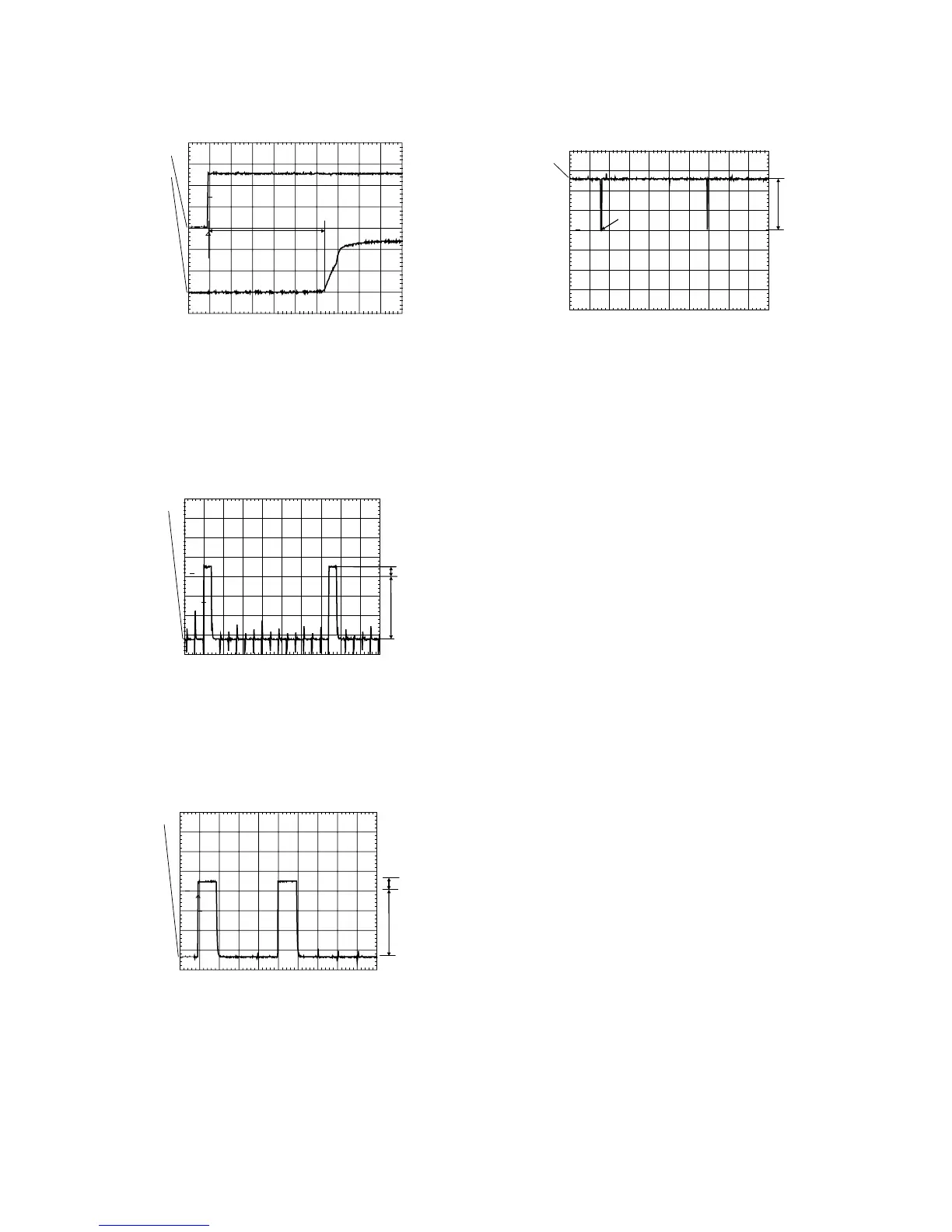
Reset
Check next reset timing with an oscilloscope at pin 10 of the
(processor.
Figure 5-11
Timing: 400msec < T1 > 700msec.
CH1: +5Vstby voltage at power on.
CH2: Voltage at pin 10.
Display steering
Check next timing and level for all grid-lines (G1 - G14).
Figure 5-12
1. Check level A: +4V5 ±10% for grid lines 1 => 11
2. Check level A: +4V0 ±10% for grid lines 12 => 14
3. Check level B: -33V ±10%
4. Check timing and levels of segment-lines P1 - P10:
Figure 5-13
Level A:+4V5 ±10%
Level B:-33V ±10%
The data on these segment lines depend on the characters
that are displayed.
The characters can be set by sending I2C commands to the
display.
See the Slave URS how to send a display command.
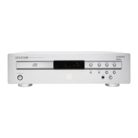
Key-matrix
Connect a extra 10k( pull-up to pin 36 en 37 of the uP and
check next matrix scanning at these pins.
Figure 5-14
Level A: 5.0V ±7%
Level B: 0V ±200mV
Check matrix scanning from pin 26 until 33 of the uP.
The results should be the same as the diagram above.
I.R. receiver
Check at pin 23 of the (P if this line switches from low (< 0.3V)
to high (> 4.5V), while pressing a key on a Philips RC5 or
RC6 remote control.
PM3392A
c h1
c h2
CH1 2. 00 V=
CH2 2 V= BW L MTB 100 ms- 1.04d v ch2+
1
2
T
T1
CL 96532065_073.eps
130799
PM3392A
ch1
ch1: low =-34.2 V
ch1: high= 3.98 V
STOP
CH1 10.0 V= MTB 200us 2324us ch1+
1
T
A
B
CL 96532065_074.eps
130799
PM3392A
ch 1
CH1 10. 0 V= BWL MTB 500u s- 1.04 dv ch1 +
1
T
A
B
CL 96532065_075.eps
130799
PM3392A
ch1
ch1: low =-46.9mV
ch1: high= 5.09 V
STOP
CH1 2.00 V= MTB10.0ms ch1-
1
B
A
CL 96532065_076.eps
130799