180
9.25 Circuit description of DAC board
9.25.1 Description
The DAC board has 6 high performance audio outputs. It
consists of 3 D/A converters and their appropriate filters, the
clock generator part, the filter-control part and the muting-
control part (See block diagram).
Key components are D/A converter CS4397 and I2C
controller PCF8574.
The DAC board supports DSD and PCM. The digital data are
sent from the MONO board to the DAC's QD41,QD51 and
QD61 via a flex and connector JD01. The audio signals are
sent to the cinches via a 2 or 1 filter stage. In these filter
stages discrete opamp's are used.
The DAC board is I2C controlled via the I2C bus from the
mono board to the DAC's and I2C controller QD21.
The differences between DSD mode and PCM mode are
shown in the table below:
Digital audio data
MCLK
9.25.2 Filter setting
The user can select 3 filter settings using switch SD71 at the
rear of the set. This is only effective during the playback of
SACD discs. See the table below.
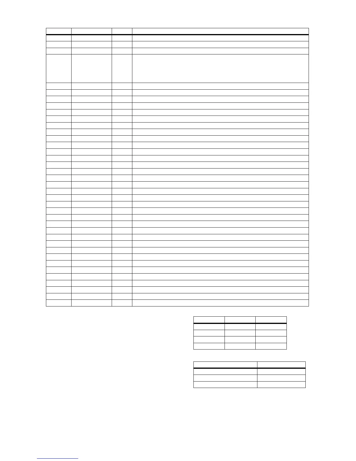
171 GND_CORE IN Ground(core)
172 PCM_dclk_Out O5 PCM data clock
173 Tst(1) IN internal pull up for both test pins
174 Tst(0) IN IC testpins tst(1:0)
11 : Functional behaviour
10 : RAM test
01 : scan shift
00 : scan normal
175 TDI IN Boundary scan Data Input.
176 TMS IN Boundary scan Mode select
177 TCK IN Boundary scan Clock
178 TDO O10 O10put
179 TRST IN Boundary scan Reset.
180 GND_IO IN Ground
181 H_IRQn O5 Interrupt Request, active low
182 H_A22 IN Data Strobe, active low
183 H_A[21] IN Address bus
184 H_A[20] IN Address bus
185 H_A[19] IN Address bus
186 H_A[18] IN Address bus
187 H_A[17] IN Address bus
188 H_A[16] IN Address bus
189 H_A[15] IN Address bus
190 H_A[14] IN Address bus
191 H_A[13] IN Address bus
192 H_A[12] IN Address bus
193 H_A[11] IN Address bus
194 H_A[10] IN Address bus
195 VCC_CORE IN 3.3V power supply Core
196 GND_CORE IN Ground(core)
197 H_A[9] IN Address bus
198 H_A[8] IN Address bus
199 H_A[7] IN Address bus
200 H_A[6] IN Address bus
201 H_A[5] IN Address bus
202 H_A[4] IN Address bus
203 H_A[3] IN Address bus
204 H_A[2] IN Address bus
205 H_A[1] IN Address bus
206 VCC_IO IN 3.3V power supply IO
207 H_DQ[15] I/O5 Data bus
208 H_DQ[14] I/O5 Data bus
IC-Pin_no Name Type Function
Pin number PCM mode DSD mode
11 BCK BCK
12 LRCK SEL_DSD
13 SDT DSD_L
14 SEL_PCM DSD_R
AUDIO SIGNAL MCLK
DSD(SACD) 192Fs(8.4672 MHz)
PCM audio (Fs = 44.1 kHz) (CD) 384Fs(16.9344 MHz)
PCM audio (Fs = 32,4896 kHz) 256Fs