176
9.24 Description of Furore IC
9.24.1 General Description
FURORE-IC is a one-chip design containing all the hardware
required for SACD processing. It is intended to interface to
the Sti family (Sti5505/Sti5508) DVD video decoders.
The FURORE-IC contains a memory interface to support one
4M*16 SDRAM or one 1M*16 SDRAM device.
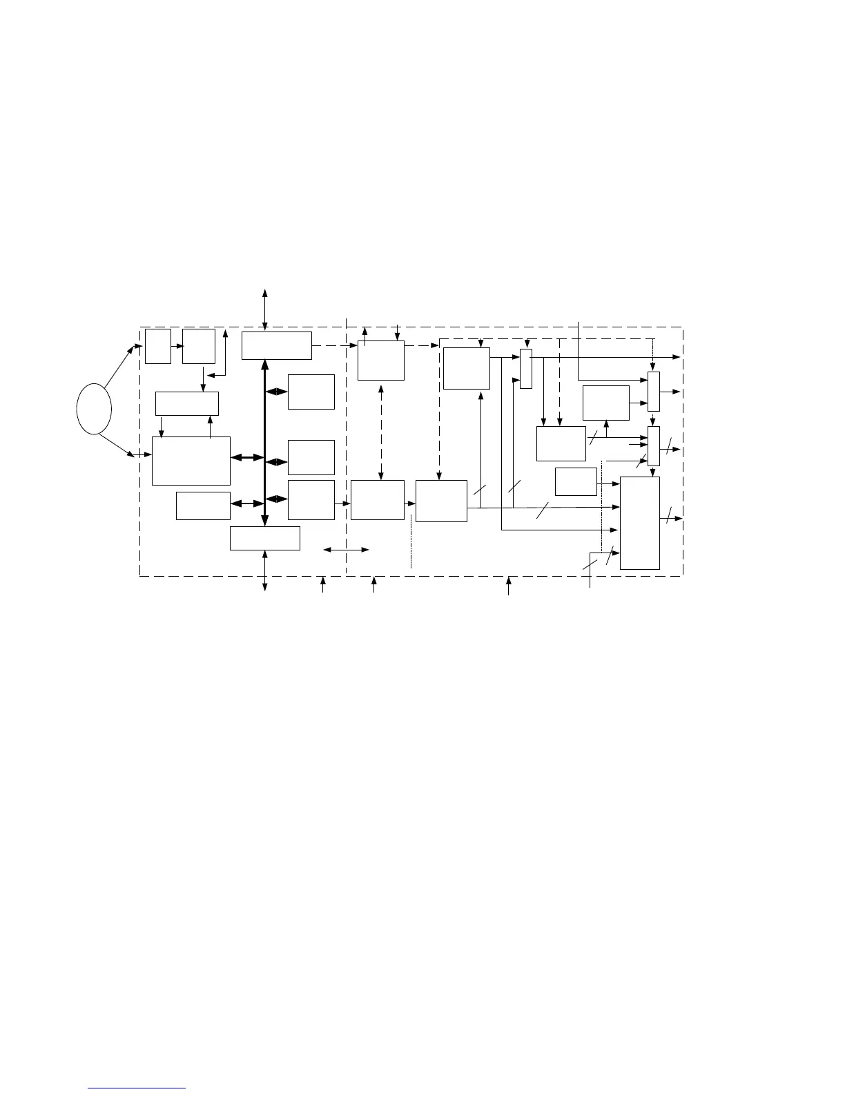
9.24.2 Blockdiagram
Figure 9-7
9.24.3 Basic Engine Interface
Data input interface.
The Basic Engine Interface is connected to the output of the
SAA7335 (HD61)
Analogue HF input
The analogue HF input, coming from the optical pickup unit,
is also fed to the Furore IC to extract the copyprotection
information "PSP".
9.24.4 SDRAM Interface
The SDRAM interface forms a glueless interface to one
16Mbit or one 64 Mbit SDRAM device.
The interface takes care for the power-up sequence, mode
programming and refreshing of the SDRAM devices. This is
hard coded in the interface and doesn't have to be controlled
by the host.
9.24.5 Audio data input/output Interface
DSD/PCM combined data output.
DSD_PCM : Output intended for a combined 6 channel DSD
( SACD ) and PCM ( DVD-CDDA) DAC. Switching between
the PCM data coming from the Sti5505 and the internal
generated DSD signals is done in the Furore IC.
Stereo DSD only output.
DSD_stereo: 2 channel DSD output, with stereo down mix in
the case of 5 and 6 channel and normal stereo in case of 2
channel DSD mode.
Stereo PCM data output.
Two possible stereo sources can be selected as stereo PCM
output:
– Stereo PCM coming from the Sti5505 via the PCM input
on Furore.
– Stereo or down mix PCM derived via a decimation filter
from the SACD-DSD signal.
Digital audio output interface (IEC958)
The IEC958 format is intended to connect the SA12S1 to
a digital receiver. No DSD signals are defined for IEC958
therefore the DSD-->PCM converted signal will be
transmitted. Following two types of signals are possible on
the digital interface:
– IEC958 data coming from Sti5505.
– IEC958 data, Stereo or down mix PCM, derived via a
decimation filter from the SACD-DSD signal.
Clock + reset input.
Two different processing clocks are needed in the FURORE-
IC:
– Sys_clk: System clock for data processing part,
frequency can be 27 MHz or 768 * Fs.
– 384 * Fs: Processing clock for LLD and postprocessing.
Decryption
/
Sector
Processor
AGC
8 bits
AD
PSP-key
decoder
Key
Host interface
Demux
SDRAM
interface
SACD
Audio
interface
PI-Bus
Control
2 -5 -6 ch
LossLess
decoder
6 channel
fade
384 * fs
sys_clk
6 * DSD
To Host
(ST5505 or ST5508)
to 16 Mbit
SDRAM
DSD to
PCM
conversion
6 channel
mix
DSD_str
PI-bus
Control
S
e
l.
Register
Host
interface
BE-
I/F
SSM
LLD
Post processing
clk_gen
384 * fs
6
3
L/R/C
6
IEC958
HF
I2S
Memory
manager
switch
matrix
IEC958
gen
S
e
l.
S
e
l.
IEC958
from Sti
PCM from Sti
5505
6
dsd_mute
4
I2S-LR +
mute
3
9
to
DSD/PCM
DAC
5
PCM data
5
sys_clk
ad(6:0)
clk_256_sacd
clk_256_dvd
gp_ingp_out
CL 06532152_098.eps
131200