181
* Normal: output via 1 filter stage (3rd order filter)
Custom: output via 2 filter stage (6th order filter)
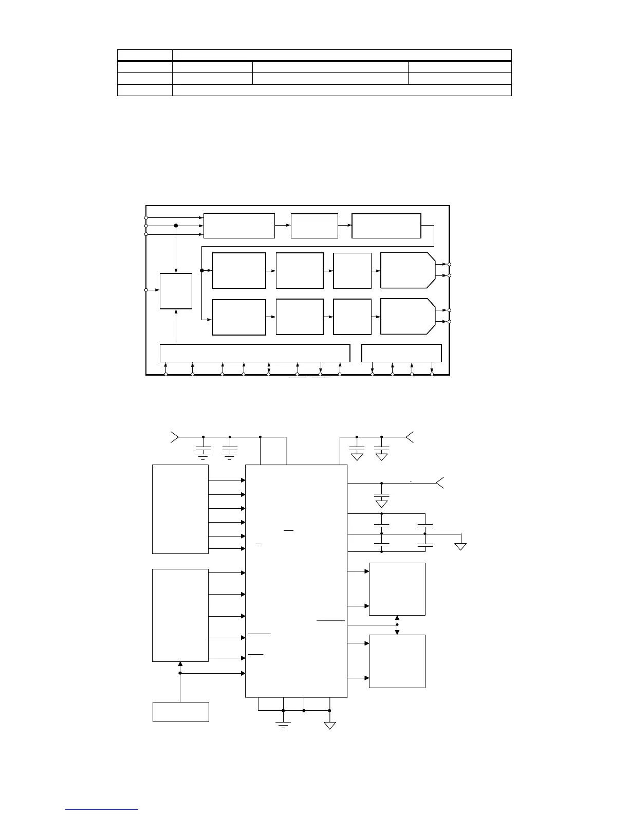
9.25.3 Description of DAC CS4397
DISCS Filter switch position
Position 1 position 2 position 3
SACD (DSD) All channels: Normal* L and R: Custom* Other channels: Normal All channels: Custom
CD (PCM) All channels : Custom
SCLK
MCLK
M4
LRCK
SDATA
AOUTL+
AOUTR+
SERIAL INTERFACE
AND FORMAT SELECT
INTERPOLATION
SOFT MUTE
DS
MODULATOR
DYNAMIC
DE-EMPHASIS
SWITCHED
AOUTL-
AOUTR-
FILT+
FILTER
INTERPOLATION
FILTER
FILTER
MULTI-BIT
DS
MODULATOR
MULTI-BIT
ELEMENT
MATCHING
LOGIC
DYNAMIC
ELEMENT
MATCHING
LOGIC
CAPACITOR-DAC
AND FILTER
SWITCHED
CAPACITOR-DAC
AND FILTER
VREF CMOUTFILT-
VOLTAGE REFERENCE
HARDWARE MODE CONTROL
CLOCK
DIVIDER
(CONTROL PORT)
(AD0/CS)
M3 M2
(AD1/CDIN) (SCL/CCLK)
M1
M0
(SDA/CDOUT)
RESET MUTEC MUTE
SCLK
Audio
Data
Processor
External Clock
MCLK
AGND
AOUTR+
CS4397
SDATA
VA
AOUTR-
+5V
Analog
+
Mode
Select
(Control Port)
M1 (GND)
M0 (SDA/CDOUT)
AOUTL-
AOUTL+
DGND
VD
MUTE
Analog
Conditioning
Analog
Conditioning
7
22
24
23
19
20
189
1
15
13
11
12
4
14
5
M2 (SCL/CCLK)
LRCK
+
RST
10
M3 (AD1/CDIN)
M4 (AD0/CS)
2
3
25
26
27
VREF
FILT+
FILT-
+5V
Analog
28
6
21
MUTEC
8
17
+
+
CMOUT
VD
16
C/H
+5 to +3 V
Digital
Typical Connection Diagram - Hardware Mode (Control Port Mode)
CS4397
Block Diagram
Pin Configuration
CL 06532152_099.eps
131200