182
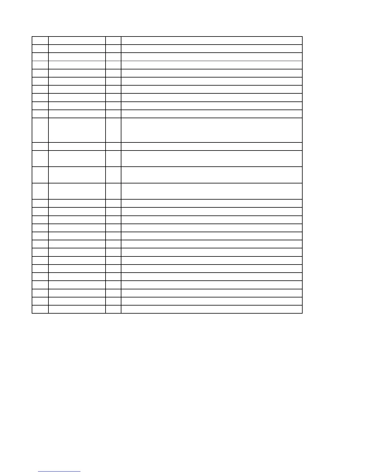
Pin Function
No. Pin Name I/O Description
1 RST I Reset input (Low active)
2 M4(AD0/CS) I Chip address bit0 for I2C
3 M3(AD1/CDIN) I Chip address bit1 for I2C
4 M2(SCL/CCLK)) I Serial clock for I2C
5 M0(SDA/CDOUT) I/O Serial data for I2C
6 DGND Digital ground
7 VD Digital power supply +3.3V
8 VD Digital power supply +3.3V
9 DGND Digital ground
10 MCLK I Master clock
PCM mode:256Fs
DSD mode:192Fs (8.4672MHz)
11 SCLK I Serial data clock
12 LRCK(PCM) I PCM mode:Left/Right channel clock
CLKMODE(DSD) I DSD mode:Select MCLK to DSD data rate clock rations
13 SDATA(PCM) I PCM mode:Serial audio data
DSD_L(DSD)
DSD mode:Direct Stream Digital audio data (Left)
14 M1(PCM) I PCM mode:(Low)
DSD_R(DSD) DSD mode:Direct Stream Digital audio data (Right)
15 MUTE I Mute input (Low active)
16 C/H I Control port (H) /Hardware (L) mode select
17 MUTEC O Mute control (Low active)
18 AGND Analog ground
19 AOUTR- O Right channel negative Analog out
20 AOUTR+ O Right channel positive Analog out
21 AND Analog ground
22 VA Analog power supply +5.5V
23 AOUTL+ O Left channel positive Analog out
24 AOUTL- O Left channel negative Analog out
25 CMOUT O Common mode voltage
26 FILT- I Reference ground
27 FILT+ O Reference filter
28 VREF Voltage reference input
CL 06532152_100.eps
131200