150
DSP for CD and DVD-ROM systems
SAA7335
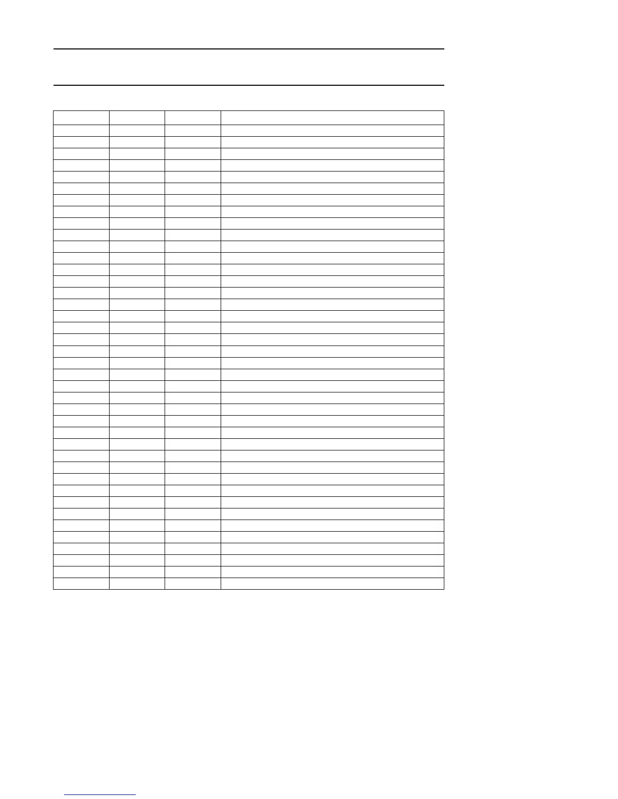
PINNING
SYMBOL PIN TYPE DESCRIPTION
V
SSA1
1 supply analog ground 1
I
ref
2 I analog current reference input for ADC
REFLo 3 I analog low reference input for ADC
REFHi 4 I analog high reference input for ADC
VREF 5 I analog negative input
HFIN 6 I analog positive input
V
SSA2
7 supply analog ground 2
AGCOUT 8 O analog test pin output
V
DDA2
9 supply analog supply voltage 2
V
DDD1
10 supply digital supply voltage 1
V
SSD1
11 supply digital ground 1
OTD 12 I off track detect input
MOTO1 13 O 3-state motor control output
n.c. 14 − not connected, reserved
MOTO2/T3 15 I/O motor control output/tachometer 3 input
n.c. 16 − not connected, reserved
T1 17 I tachometer 1 input
T2 18 I tachometer 2 input
V
DDD2
19 supply digital supply voltage 2
V
SSD2
20 supply digital ground 2
TEST1 21 I test input 1
TEST2 22 I test input 2
POR 23 I power-on reset input
MUXSWICH 24 I use clock multiplier input
n.c. 25 − not connected, reserved
CL1 26 O divided clock output
BCAIN 27 I BCA input
SDA 28 I/O sub-CPU I
2
C-bus serial data input/output
SCL 29 I sub-CPU I
2
C-bus serial clock input
INT 30 O sub-CPU interrupt output (open-drain)
V
DDD3
31 supply digital supply voltage 3
V
SSD3
32 supply digital ground 3
da7 33 I/O sub-CPU data bus bit 7 input/output (parallel)
da6 34 I/O sub-CPU data bus bit 6 input/output (parallel)
da5 35 I/O sub-CPU data bus bit 5 input/output (parallel)
n.c. 36 − not connected, reserved
da4 37 I/O sub-CPU data bus bit 4 input/output (parallel)
n.c. 38 − not connected, reserved
da3 39 I/O sub-CPU data bus bit 3 input/output (parallel)
da2 40 I/O sub-CPU data bus bit 2 input/output (parallel)