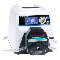
2-11 Masterflex
®
I/P
®
MasterSense™ Process Drives
Section 2: Basic Setup & Settings
Masterflex
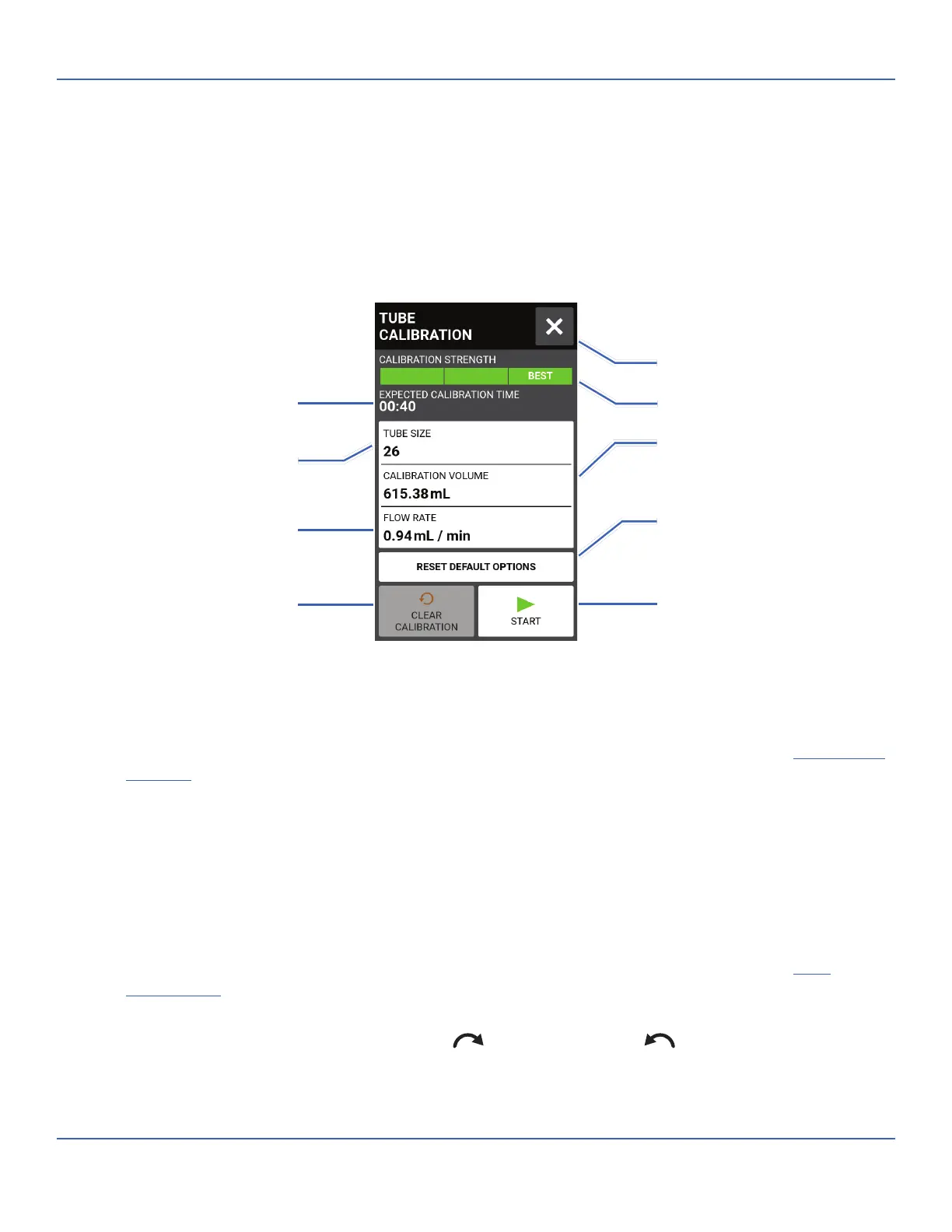
TUBE CALIBRATION
To ensure accurate dispensing of uids, tube calibration should be performed whenever uids, ow rate or
tubing is changed. Tube calibration can be accessed from the Continuous Mode Run Screen or from either of
the Volume or Time Mode Edit screens.
Tube Calibration Screen
General Preparation:
• Con rm the correct tubing has been selected and is properly loaded into the pump drive (refer to the
pump head user manual for further information).
• Ensure the correct pump head and tube size have been selected (for further information see "
Pump Head
Selection
" on page 2-9).
• Con rm all uids and containers are ready.
To calibrate tubing:
1. Insert the tube inlet into the supply uid.
2. Insert the tube outlet into a suitable container. NOTE: e container should be placed on a scale for
increased accuracy. If using a scale, an acceptable weight to volume conversion for water is: 1 g = 1 mL.
3. Switch the drive on using the power switch located at the rear of the drive. NOTE: If User Management
is enabled you may be prompted for a username and password (For further information see "
User
Management
" on page 2-8).
4. Navigate to the Continuous, Time or Volume Mode screens.
5. Tap DIRECTION to select either clockwise
or counterclockwise ow direction.
Selected Tube Size
Approximate Duration
Set Flow Rate
Clear Calibration Settings
Calibration Volume
Default Cycle Options
Calibration Strength Bar
Return to Previous Screen
Start Calibration
Tap to reset the calibration
volume and flow rate to their
default settings