112 CONTENTS
Choose either "DigIn0" if signal is connected to "IN0" or DigIn1 if signal is connected to IN1. In general entry "←-
RTCtrl" is not useful in this case because triggering would be controlled by Hardware Real-Time Controller
(p. 124) which is not described here and also not necessary.
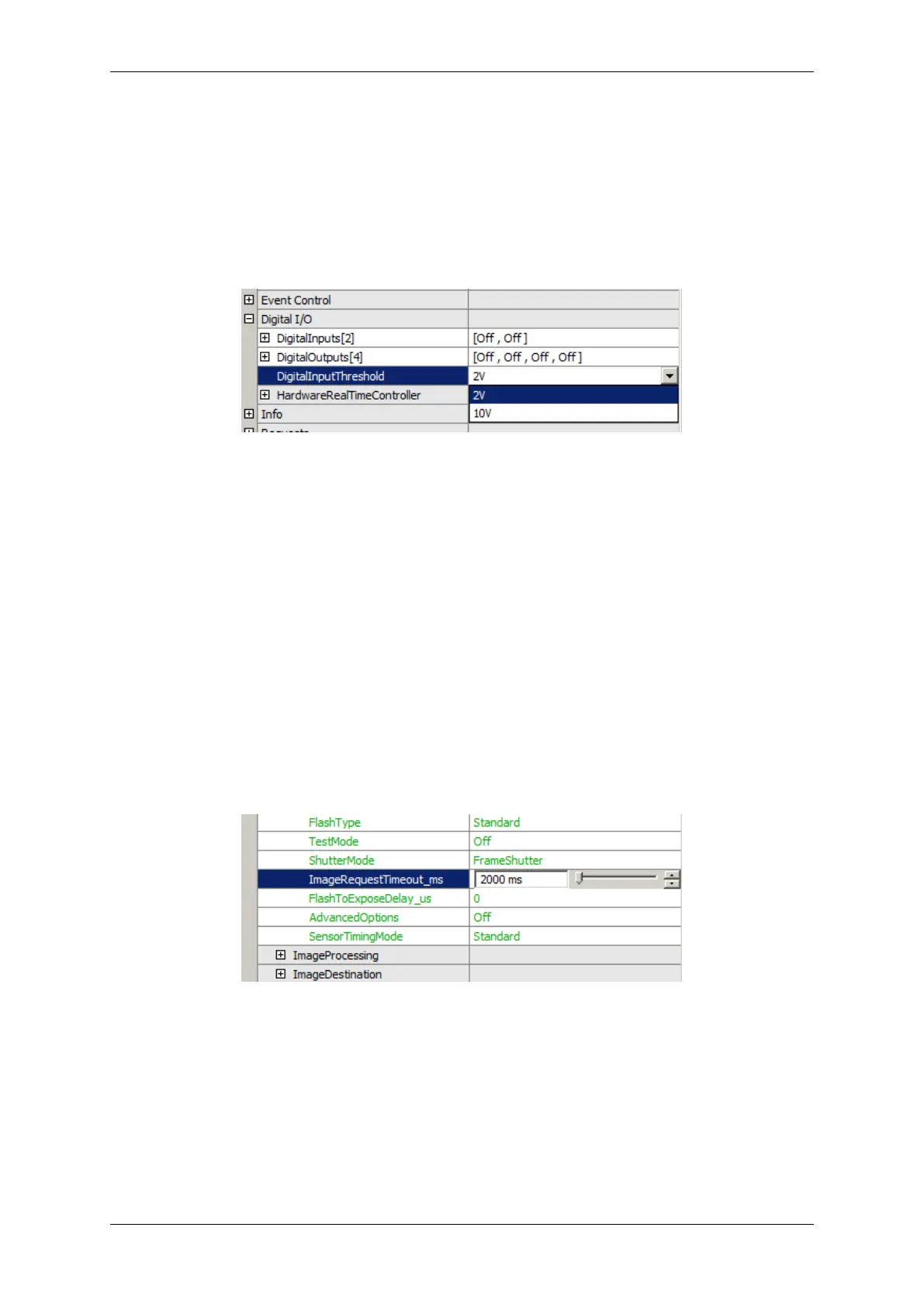
Depending on voltage level you are using for trigger signal you must choose the "DigitalInputThreshold":
Figure 41: DigitalInputThreshold
In case of TTL choose 2V and in case of PLC choose 10V.
Now, the image acquisition runs corresponding to external trigger signal and trigger mode. You will see the acquired
images on the left part of the window. Preview will be updated in frequency of external trigger.
The program knows a timeout period within at least one trigger signal must be provided to the camera. If no trigger
signal comes within this time, no image is acquired and an error is set (error count increases). So be sure to set
this timeout period to a value, which is long enough to receive at least one trigger signal. You can set this value in
"ImageRequestTimeout" property:
Figure 42: ImageRequestTimeout
Trigger
To activate flash control signal set "FlashMode" to the output you connected flash or flash driver to:
MATRIX VISION GmbH
 Loading...