11.1 wxPropView 113
Figure 43: External flash signal
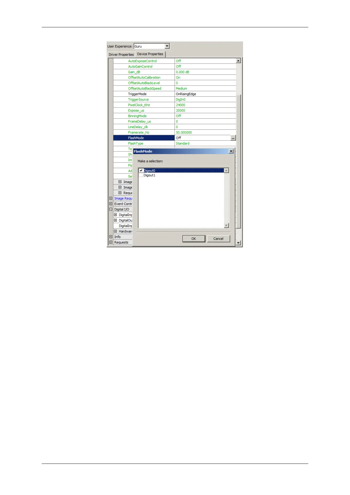
Since this mode is activated each image acquisition will generate the flash signal. This generation is independent
from used trigger mode. Flash signal is directly derived from integration timing.
This means that if no "FlashToExposureDelay" is set flash signal will rise as soon as integration starts and fall when
integration is finished. The pulse width cannot be changed. So you can be sure that integration takes place when
trigger signal is high.
11.1.2.6 Working with the hardware Look-Up-Table (LUT)
There are two parameters which handles the pixel formats of the camera:
• "Setting -> Camera -> PixelFormat" defines the pixel format used to transfer the image data into the target
systems host memory.
• "Setting -> ImageDestination -> PixelFormat" defines the pixel format of the resulting image (which is kept
in the memory by the driver).
If both formats are set to "Auto", 8 bit will be used.
If you set "LUTImplementation" to "Software" in "Setting -> ImageProcessing -> LUTOperations", the hardware
Look-Up-Table (LUT) will work with 8 bit data ("LUTMappingSoftware = 8To8"). Using Gamma functions you will
see gaps in the histogram:
MATRIX VISION GmbH
 Loading...