8.3 Board-level version (mvBlueFOX-Mxxx) 53
See also
UserDataEntry class description
8.3.1.1 4-pin Wire-to-Board header (USB 2.0)
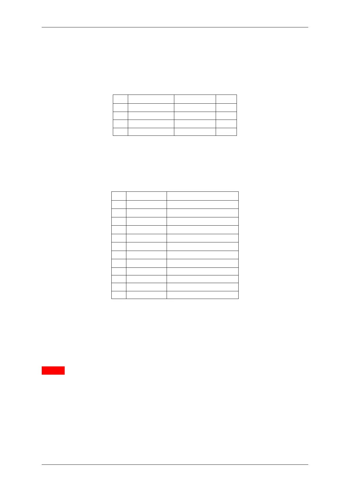
Pin Signal Comment Cable
1 USBPOWER_IN Supply voltage red
2 USB_DATA- Data white
3 USB_DATA+ Data green
4 GND Ground black
Manufacturer: JST
Part number: B4B-PH-K
8.3.1.2 12-pin Wire-to-Board header (Dig I/O)
Pin Signal Comment
1 FPGA_IO0 Digital In 0
2 FPGA_IO1 Digital In 1
3 FPGA_IO2 Digital In 2
4 FPGA_IO3 Digital In 3
5 FPGA_IO4 Digital Out 0
6 FPGA_IO5 Digital Out 1
7 FPGA_IO6 Digital Out 2
8 FPGA_IO7 Digital Out 3
9 MAINPOWER Current from the USB cable
10 GND Ground
11 VCC24V 24 V output (10mA)
12 GND Ground
Manufacturer: JST
Part number: B12B-PH-K
Attention
Do not connect Dig I/O signals to the FPGA pins until the mvBlueFOX-M has been started and configured.
Otherwise, you will risk damaging the mvBlueFOX-M hardware!
MATRIX VISION GmbH