146 Appendix B: Technical information
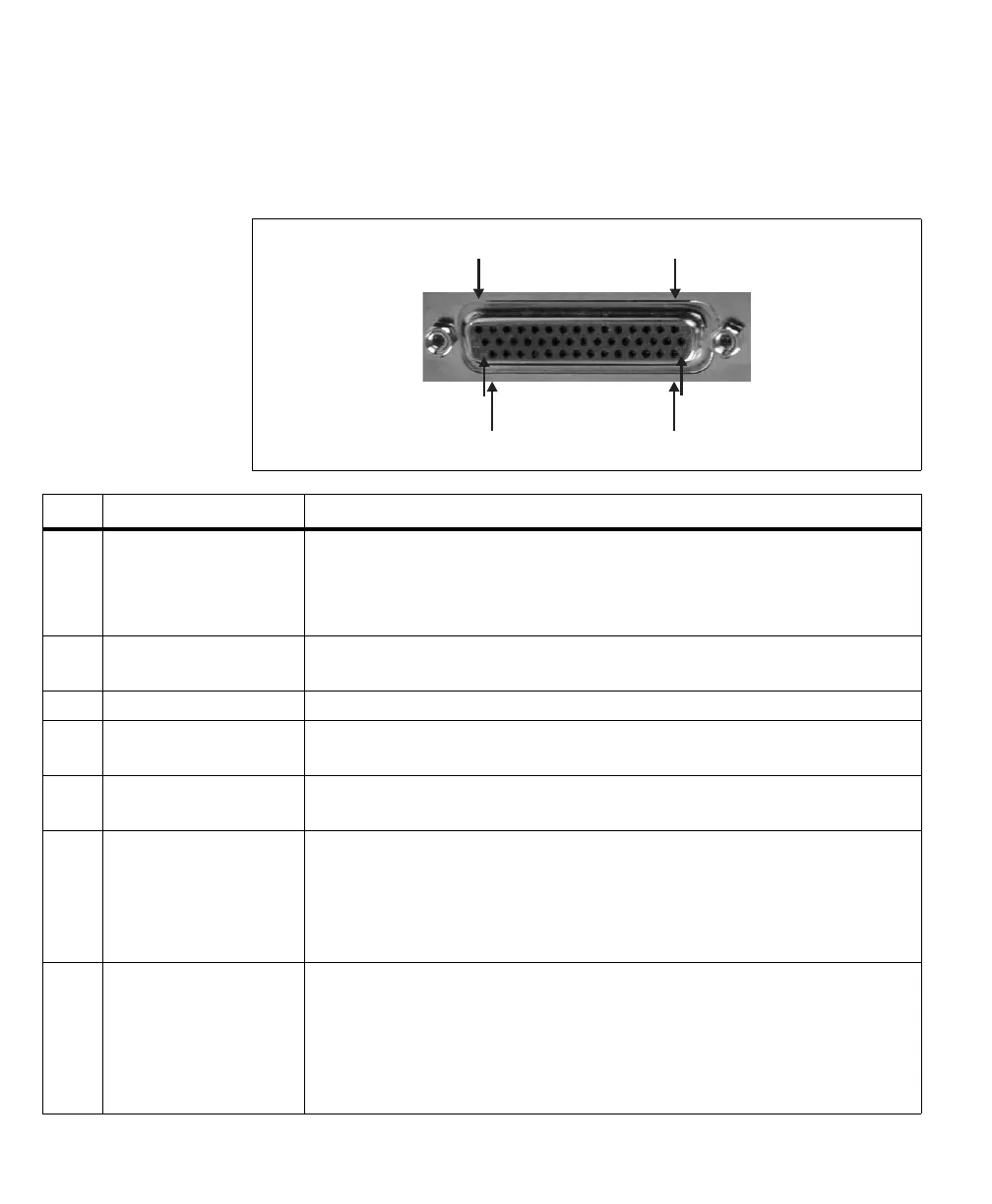
The pinout for this connector is as follows. The description of each (positive)
auxiliary signal states whether the signal is specific to an acquisition path and the
type of signals that can be routed onto it.
1
16
31
15
30
44
Pin
Signal
1
Description
1 LVDS/TTL_AUX_IN7+ Auxiliary input 7 for an unspecified acq. path (positive).
Signals only supported for acq. path 0, 1, and 2: user-defined input 9.
Signals only supported for acq. path 3: user-defined input 3, timer clock, or VSYNC input.
Signals supported for any acq. path: trigger input 3.
2 P3_LVDS/TTL_AUX_OUT1+ Auxiliary output 1 for acq. path 3 (positive).
Supported signals: user-defined output 1, exposure output 1, or VSYNC output.
3 GND Ground.
4 P2_LVDS/TTL_AUX_OUT1- Auxiliary output 1 for acq. path 2 (negative).
See pin 20 for more information.
5 LVDS/TTL_AUX_IN5- Auxiliary input 5 for an unspecified acq. path (negative).
See pin 6 for more information.
6 LVDS/TTL_AUX_IN5+ Auxiliary input 5 for an unspecified acq. path (positive).
Signals only supported for acq. path 0 and 1: user-defined input 7.
Signals only supported for acq. path 2: user-defined input 3, or timer clock or VSYNC input.
Signals only supported for acq. path 3: user-defined input 9.
Signals supported for any acq. path: trigger input 3.
7 LVDS/TTL_AUX_IN4+ Auxiliary input 4 for an unspecified acq. path (positive).
Signals only supported for acq. path 0 and 1: user-defined input 6.
Signals only supported for acq. path 2: user-defined input 2, or field, data valid, CSYNC, or HSYNC
input.
Signals only supported for acq. path 3: user-defined input 8.
Signals supported for any acq. path: trigger input 2.