Matrox Solios eCL/XCL acquisition section 63
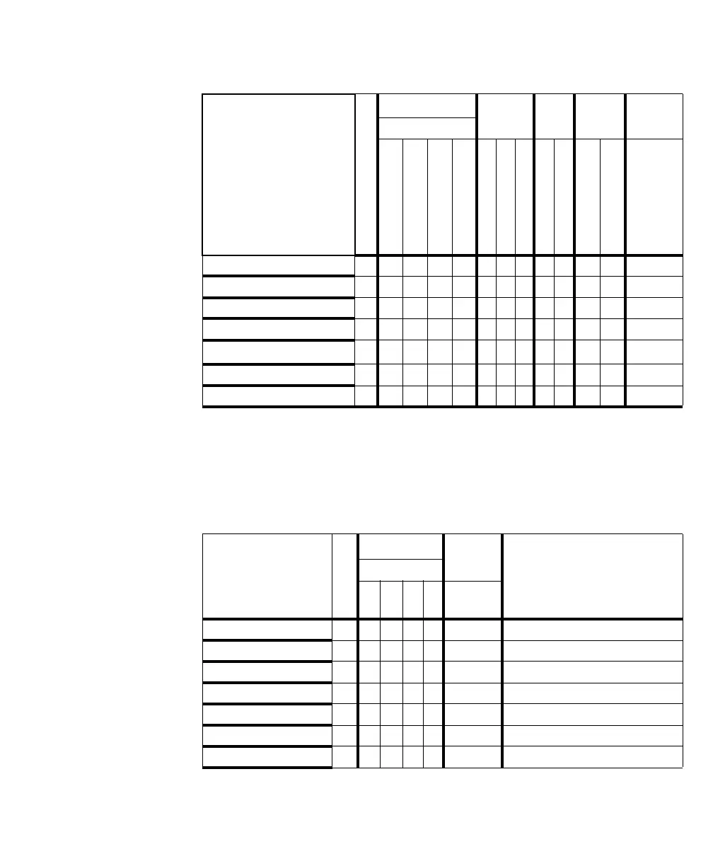
Type of signal
Max # signals
1
1. The maximum # for each signal type cannot always be attained. The actual maximum depends on whether the required aux-
iliary signals are available or have been defined as another type.
LVDS cam. ctrl
TTL aux.
I/O
2
2. On auxiliary I/O connector (DB-15).
OPTO
aux. in
2
LVDS
aux. in
2
LVDS
aux. out
2
CL connect.
CC1
CC2
CC3
CC4
P0_TTL_AUX_IO_0
P0_TTL_AUX_IO_1
3
3. Not available when the DB-15 auxiliary I/O connector is replaced with the optional DB-9 connector from the
SOLCLBACCxxPAK accessory kit.
P0_TTL_AUX_IO_2
3
P0_OPTO_AUX_IN0
P0_OPTO_AUX_IN1
P0_LVDS_AUX_IN0
P0_LVDS_AUX_IN1
3
P0_LVDS_AUX_OUT0
3
Exposure output 4 0/1 0/1 0/1 0/1 2 0/3 1 0
Trigger input 3 01201 0 1
Field polarity input 1000
Timer-clock input 10
Quadrature input
4
4. Note that a rotary encoder with quadrature output transmits a two-bit code. The table entries 0 and 1, therefore, denote bit
position.
101
User-defined input 7 23401 5 6
User-defined output 6 0/1 0/1 0/1 0/1 2 3 4 5
Type of signal
Max # signals
1
1. The maximum # for each signal type cannot always be attained. The actual maximum depends on whether the required aux-
iliary signals are available or have been defined as another type.
LVDS cam. ctrl Received
with data
LVDS dedicated signals
2
2. In this column, each signal is a dedicated signal (that is, it cannot be redefined as another type of signal).
CL connect.
CC1
CC2
CC3
CC4
CL
connect.
Frame valid input 10
VSYNC output 10000
Line valid input 10
HSYNC output 10000
Data valid input 10
Clock input 1 Xclk (CL connect.)
Clock output 10000