64 Chapter 4: Matrox Solios hardware reference
Matrox Solios eCL/XCL dual-Base/single-Medium and eCL/XCL-F
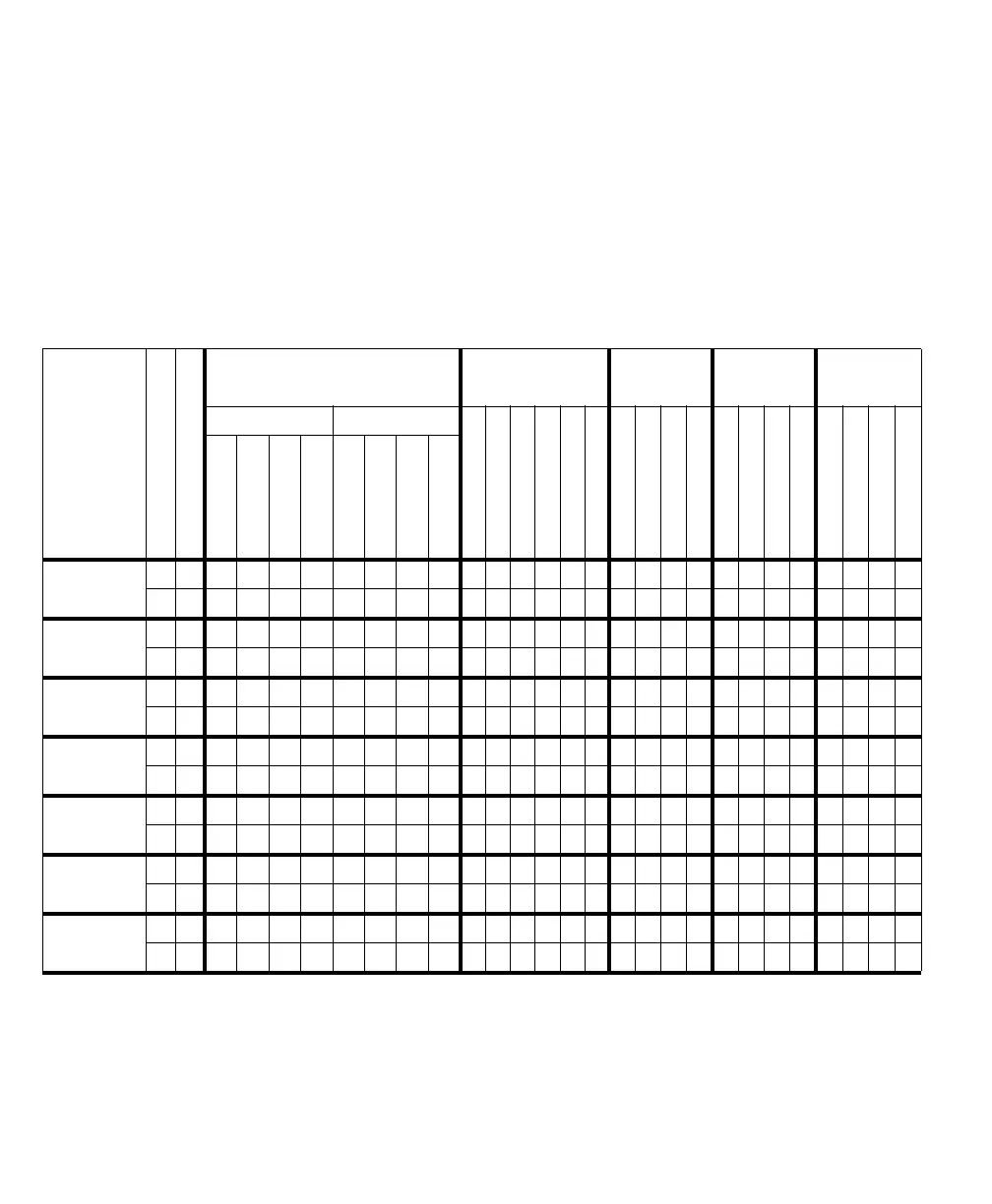
The following tables summarize the synchronization, timing, and control signals
supported by Matrox Solios eCL/XCL dual-Base/single-Medium and Matrox
Solios eCL/XCL-F. For example, P0_TTL_AUX_IO_0 can be defined for
acquisition path 0 as exposure output signal 2, trigger input signal 0, field polarity
input signal 0, user-defined input signal 2, or user-defined output signal 2. Note,
signals defined for acquisition path 1 do not apply to the single-Medium and
single-Full configurations. CL connect. stands for Camera Link connector.
Type of
signal
Path#
Max # signals
1
LVDS cam. ctrl TTL aux. I/O
2
OPTO aux. in
2
LVDS
aux. in
2
LVDS aux. ou t
2
CL connect. 0 CL connect. 1
P0_TTL_AUX_IO_0
3
P0_TTL_AUX_IO_1
P1_TTL_AUX_IO_0
P1_TTL_AUX_IO_1
TTL_AUX_IO_0
TTL_AUX_IO_1
P0_OPTO_AUX_IN0
3
P0_OPTO_AUX_IN1
3
OPTO_AUX_IN0
OPTO_AUX_IN1
P0_LVDS_AUX_IN0
3
P0_LVDS_AUX_IN1
LVDS_AUX_IN0
LVDS_AUX_IN1
P0_LVDS_AUX_OUT0
P0_LVDS_AUX_OUT1
P1_LVDS_AUX_OUT0
P1_LVDS_AUX_OUT1
CC1
CC2
CC3
CC4
CC1
CC2
CC3
CC4
Exposure
output
0 4 0/10/10/10/1 20/3 1 0 1
1 4 0/1 0/1 0/1 0/1 2 0/3 1 0 1
Trigger input 0 4 01 2301230123
1 4 0 1 2 3 0/2 1/3 0/2 1/3
Field polarity
input
01 0 0 0
11 0 0 0
Timer-clock
input
01 0
11 0
Quadrature
input
4
01 01
11 01
User-defined
Input
012 23 470189561011
1 8 2374 01 56
User-defined
output
0 7 0/10/10/10/1 2 3 4 7 5 6
1 7 0/1 0/1 0/1 0/1 2 3 7 4 5 6
1. The maximum # for each signal type cannot always be attained. The actual maximum depends on whether the required auxiliary signals are available or have been
defined as another type.
2. On external auxiliary I/O connector 0 (DB-44).
3. On external auxiliary I/O connector 1 (DB-9).
4. Note that a rotary encoder (starting with Matrox Solios XCL Version 100) with quadrature output transmits a two-bit code. The table entries, therefore, denote bit posi-
tion.