Matrox Solios eCL/XCL acquisition section 65
Auxiliary signals and camera control signals
Matrox Solios eCL/XCL supports multi-purpose auxiliary input and output
signals. Auxiliary signals are configurable signals that can support one or several
functions, one of which is user-defined. As mentioned previously, for each
independent acquisition path, the board also supports four camera control output
signals, which are also configurable signals that can support one or several
functions, one of which is user-defined. The table in the previous subsection
identifies the functions to which an auxiliary signal/camera control signal can be
defined. You specify their function in the DCF file.
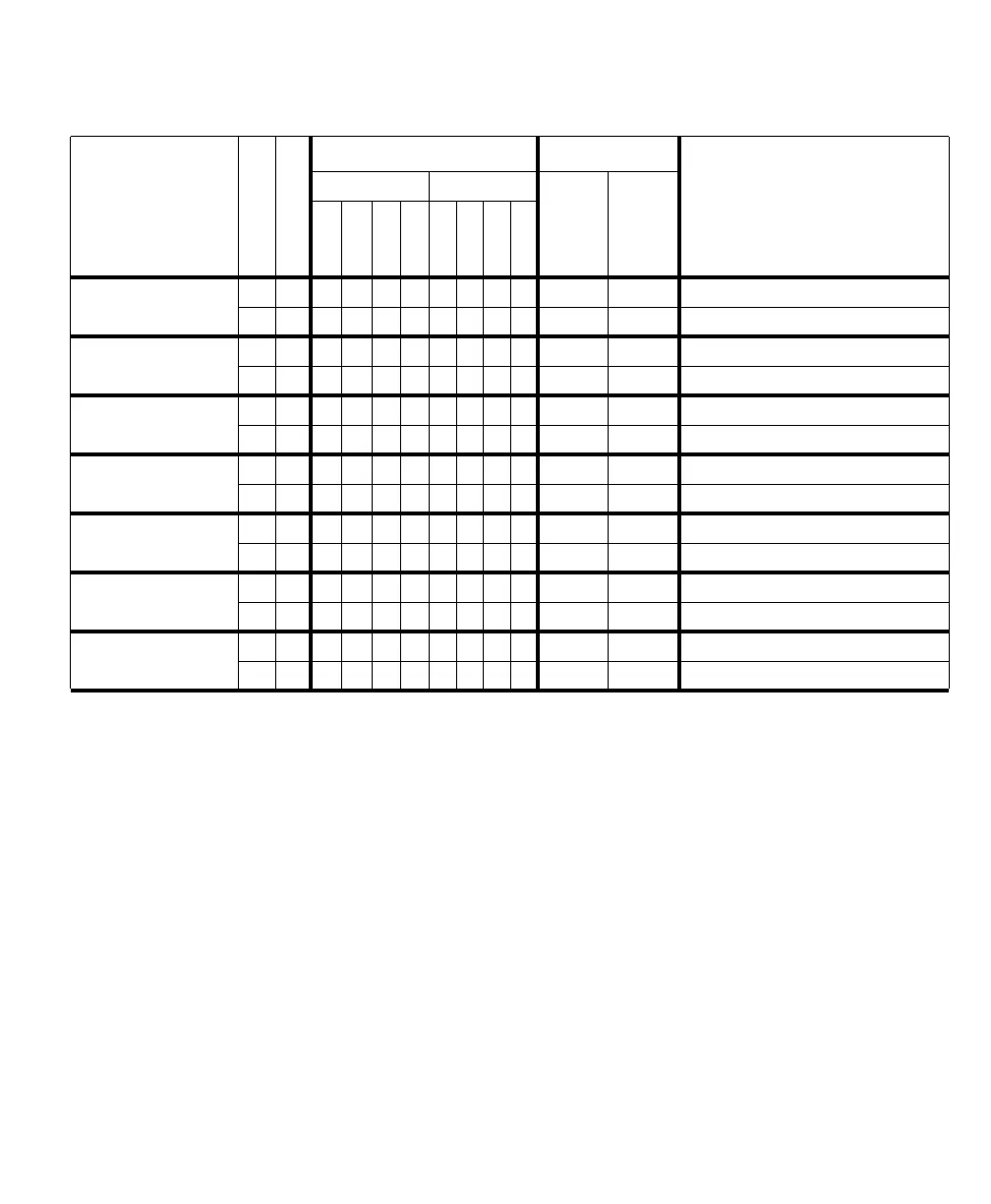
Type of signal
Path#
Max # signals
1
LVDS cam. ctrl Received with data LVDS dedicated signals
2
3
CL connect. 0 CL connect. 1
CL connect. 0
CL connect. 1
CC1
CC2
CC3
CC4
CC1
CC2
CC3
CC4
Frame valid input 01 0
11 0
VSYNC output 010000 P0_LVDS_VSYNC_OUT
1 1 0000 P1_LVDS_VSYNC_OUT
Line valid input 01 0
11 0
HSYNC output 010000 P0_LVDS_HSYNC_OUT
1 1 0000 P1_LVDS_HSYNC_OUT
Data valid input 01 0
11 0
Clock input 01 Xclk (CL connect. 0)
11 Xclk (CL connect. 1)
Clock output 010000 P0_LVDS_CLK_OUT
1 1 0000 P1_LVDS_CLK_OUT
1. The maximum # for each signal type cannot always be attained. The actual maximum depends on whether the required auxiliary signals are available or have been
defined as another type.
2. In this column, each signal is a dedicated signal (that is, it cannot be redefined as another type of signal).
3. Clock input is received on the Camera Link connectors, whereas the other signals in this column are received on/transmitted from external auxiliary I/O connector 0
(DB-44).