82 Chapter 4: Matrox Solios hardware reference
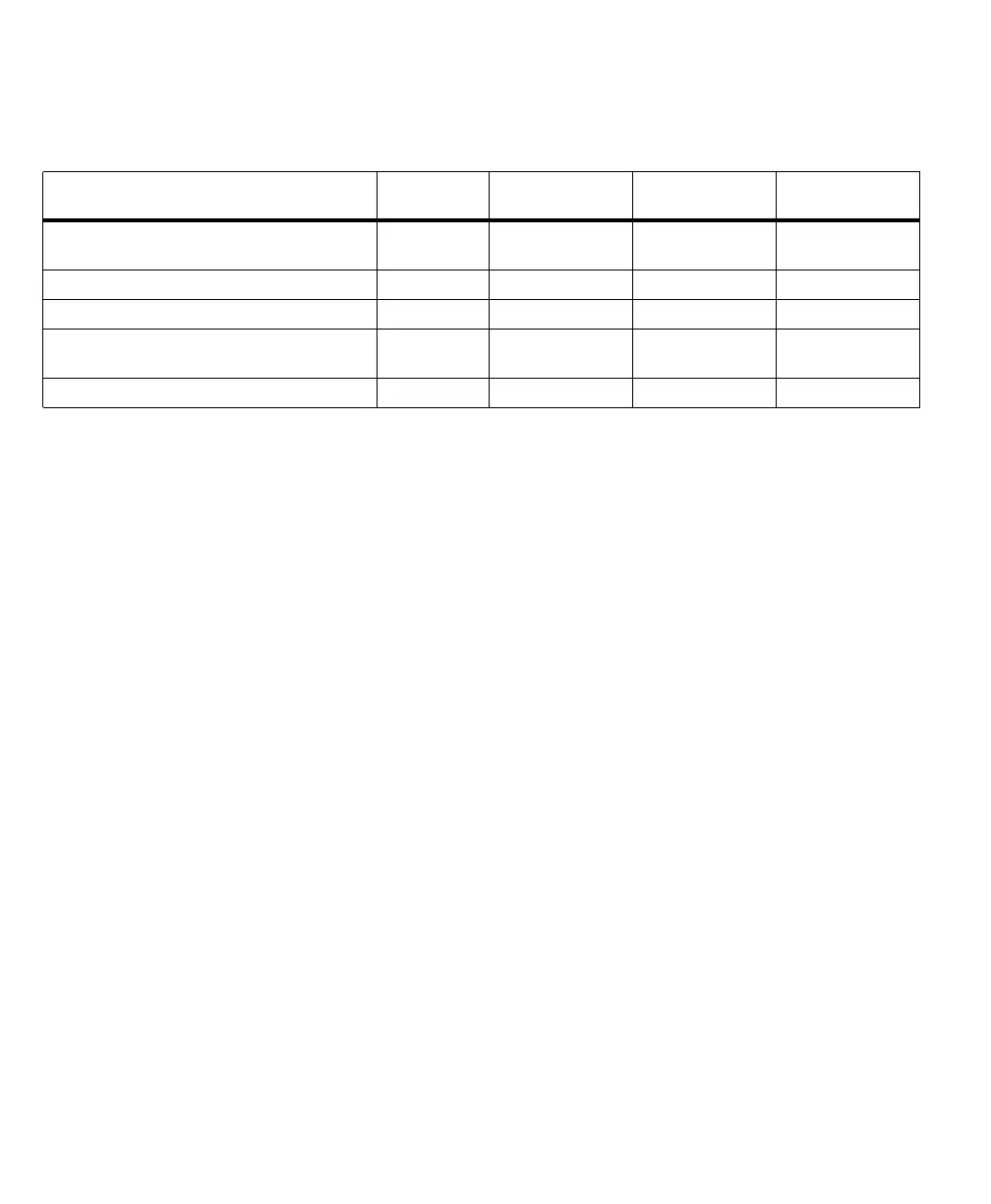
The board supports auxiliary signals in different formats:
Note that the opto-isolated signals pass through an opto-coupler, a device that
protects the board from outside surges and different ground levels, and permits
total electrical isolation from the frame grabber.
You specify the purpose of the auxiliary signals in the DCF. You can then program
these signals using the MIL-Lite function MdigControl() with
M_USER...,
M_TRIGGER..., or M_GRAB_EXPOSURE...
Synchronization
Each PSG can accept and/or provide one horizontal (HSYNC) and one vertical
(VSYNC) synchronization signal (slave or master mode). Instead of accepting a
horizontal synchronization signal, each PSG can alternatively accept a composite
(CSYNC) synchronization signal. Note also that, if the synchronization signals
are encoded on the video signal, the horizontal and vertical synchronization signals
are present as a composite synchronization pulse along with the video signal.
With interlaced video sources, you can typically establish which field is being input
by noting the phase shift between the horizontal and the vertical synchronization
signals. Alternatively, you can define an auxiliary signal as a field polarity input
signal and transmit the field polarity on this signal.
To establish which pixels are active in a line (because the horizontal
synchronization signal does not identify the blanking portion of the signal), the
board can generate a data valid signal based on information specified in the DCF.
Alternatively, you can define an auxiliary input signal as a data valid signal.
Auxiliary signals # per path Matrox Solios
eA/XA Quad #total
Matrox Solios
eA/XA Dual # total
Matrox Solios
eA/XA Single #total
Auxiliary input signals that can be defined as either
TTL or LVDS.
depends on
type of signal
888
Opto-isolated auxiliary input signals. 1 4 2 1
TTL auxiliary input signals. 1 4 2 1
Auxiliary output signals that can be defined as either
TTL or LVDS.
2842
TTL auxiliary output signals. 1 4 2 1