Matrox Solios eA/XA acquisition section 81
Auxiliary signals
Matrox Solios eA/XA supports multi-purpose auxiliary input and output signals.
Auxiliary signals are configurable signals that can support one or several functions,
one of which is user-defined. The table in the previous subsection identifies the
functions to which an auxiliary signal can be defined. You specify their function
in the DCF file.
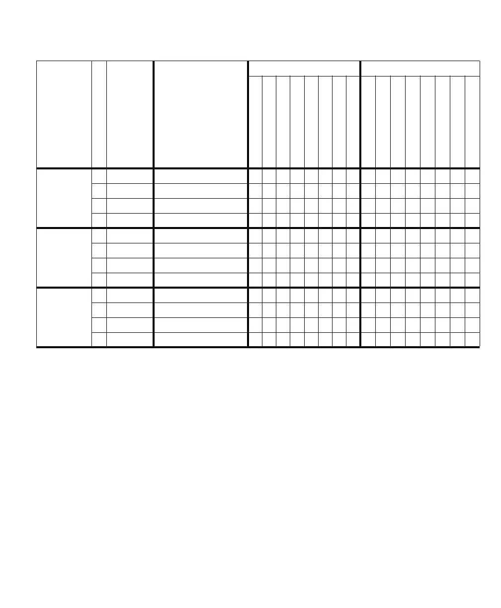
Typ e of signa l
Path#
Max # signals
1
TTL/LVDS dedicated
input/output signals
2
TTL/LVDS aux. input
3
TTL/LVDS aux. output
3
LVDS/TTL_ AU X_IN0
LVDS/TTL_ AU X_IN1
LVDS/TTL_ AU X_IN2
LVDS/TTL_ AU X_IN3
LVDS/TTL_ AU X_IN4
LVDS/TTL_ AU X_IN5
LVDS/TTL_ AU X_IN6
LVDS/TTL_ AU X_IN7
P0_LVDS/TTL_AUX_OUT0
P0_LVDS/TTL_AUX_OUT1
P1_LVDS/TTL_AUX_OUT0
P1_LVDS/TTL_AUX_OUT1
P2_LVDS/TTL_AUX_OUT0
P2_LVDS/TTL_AUX_OUT1
P3_LVDS/TTL_AUX_OUT0
P3_LVDS/TTL_AUX_OUT1
VSYNC 0 1 in +1 out P0_LVDS_TTL_VSYNC_IO in out
1 1 in + 1 out P1_LVDS_TTL_VSYNC_IO in out
2 1 in + 1 out P2_LVDS_TTL_VSYNC_IO in out
3 1 in + 1 out P3_LVDS_TTL_VSYNC_IO in out
CSYNC or
HSYNC
4
0 1 in + 1 out P0_LVDS/TTL_CHSYNC_IO in out
1 1 in + 1 out P1_LVDS/TTL_CHSYNC_IO in out
2 1 in + 1 out P2_LVDS/TTL_CHSYNC_IO in out
3 1 in + 1 out P3_LVDS/TTL_CHSYNC_IO in out
Clock 01 in/out P0_LVDS/TTL_CLK_IO
11 in/out P1_LVDS/TTL_CLK_IO
21 in/out P2_LVDS/TTL_CLK_IO
31 in/out P3_LVDS/TTL_CLK_IO
1. The maximum # for each signal type cannot always be attained. The actual maximum depends on whether the required auxiliary signals are available or have been
defined as another type.
2. In this column, each signal is a dedicated signal (that is, it cannot be redefined as another type of signal). These signals can be accessed from the DVI connectors;
the clock signal can also be accessed from the internal auxiliary I/O connector.
3. On external auxiliary I/O connector 0 (DB-44).
4. The board can accept an HSYNC or CSYNC input signal, but it can only output an HSYNC signal.