92 Chapter 4: Matrox Solios hardware reference
Specifications of the auxiliary signals
The board supports the auxiliary signals in different formats:
When an auxiliary input signal is received in TTL format directly, the signal must
have a maximum amplitude of 5 V. A signal over 2 V is considered high, while
anything less than 0.8 V is considered low; the transition of 0.8 V to 2 V is
considered to be the rising edge.
The opto-isolated auxiliary input signals pass through an opto-coupler. The
voltage difference across the positive and negative components of the signal must
be between 4.06 V and 9.165 V for logic high, and between -5.0 V and 0.8 V for
logic low.
You can set the direction of an auxiliary I/O signal using the MIL-Lite function
MdigControl() with M_AUX_SIGNAL_MODE+n, where n is a value between
6 and 9.
❖ Note that the direction of the TTL auxiliary I/O signals cannot be set
independently. You can set them either all as input or all as output signals.
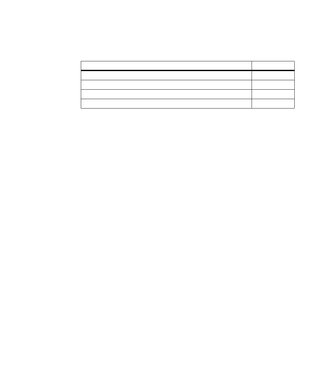
Auxiliary signals Number of signals
Opto-isolated auxiliary input signals 4
LVDS auxiliary input signals 2
TTL auxiliary I/O signals 4
TTL auxiliary output signals 8