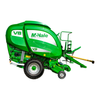
McHale Fusion 3 Baler & Wrapper
54
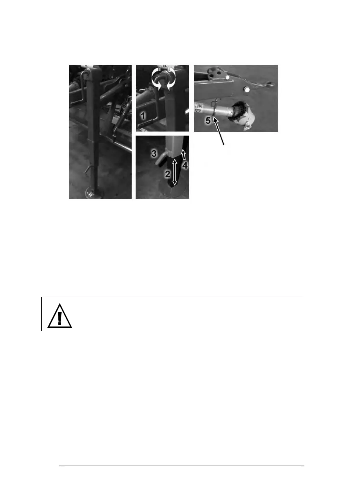
the R-clip (4)) and sliding up the lower part of the stand, fully into position.
Align the bottom hole and replace the pin (3) followed by R-clip (4).
The PTO stand (5) can be simply lifted out of the way, once the machine has
been coupled to the tractor, with the PTO shaft connected. Leave the stand in
a suitable location such as the tractor cab, toolbox, etc. available for its next
use.
Depending on the height of the windrow being baled, the stand may need to
be elevated further, in order to avoid catching crop. This is done by rotating
the jack handle (1) in a counter-clockwise direction until it is fully retracted.
6.13 Drawbar adjustment
This adjustment should be carried out on a level concrete surface, with the tractor
drawbar aligned such that the exact adjustment can be monitored. Ensure that the
tractor engine has been shut down, the ignition key removed and the brakes applied.
The machine handbrake must be applied, the main wheels chocked, with the front end
of the machine (under the chopper unit) supported on axle stands. The drawbar should
be adjusted so that the machine is level and horizontal to the ground when in the
working position, see figure “Drawbar adjustment” below. To adjust, first remove the
safety-bolts, then slacken the hinge-bolts (C), but do not remove. Hitch-eye can be
adjusted to different height positions by repositioning bolts (B) in alternating hole
positions. It can then be re-adjusted locally by loosening bolts (A & D) to ensure it is
level. Once the desired height is achieved, ensure that bolts (A & B) are tightened to a
torque value of 540 Nm and the 30 mm top drawbar hinge-bolts (C) tightened to a
torque value of 1060 Nm. Tighten bolt (D) and reposition and tighten safety-bolts.
WARNING: Adjustment to be completed by qualified persons only
This work should only be carried out by qualified persons or your
McHale dealer!
1