McHale Fusion 3 Baler & Wrapper
81
3. Place spare knife in the working position and place a new spare knife
underneath, if available.
4. Tighten the two M6 setscrews to 12 Nm.
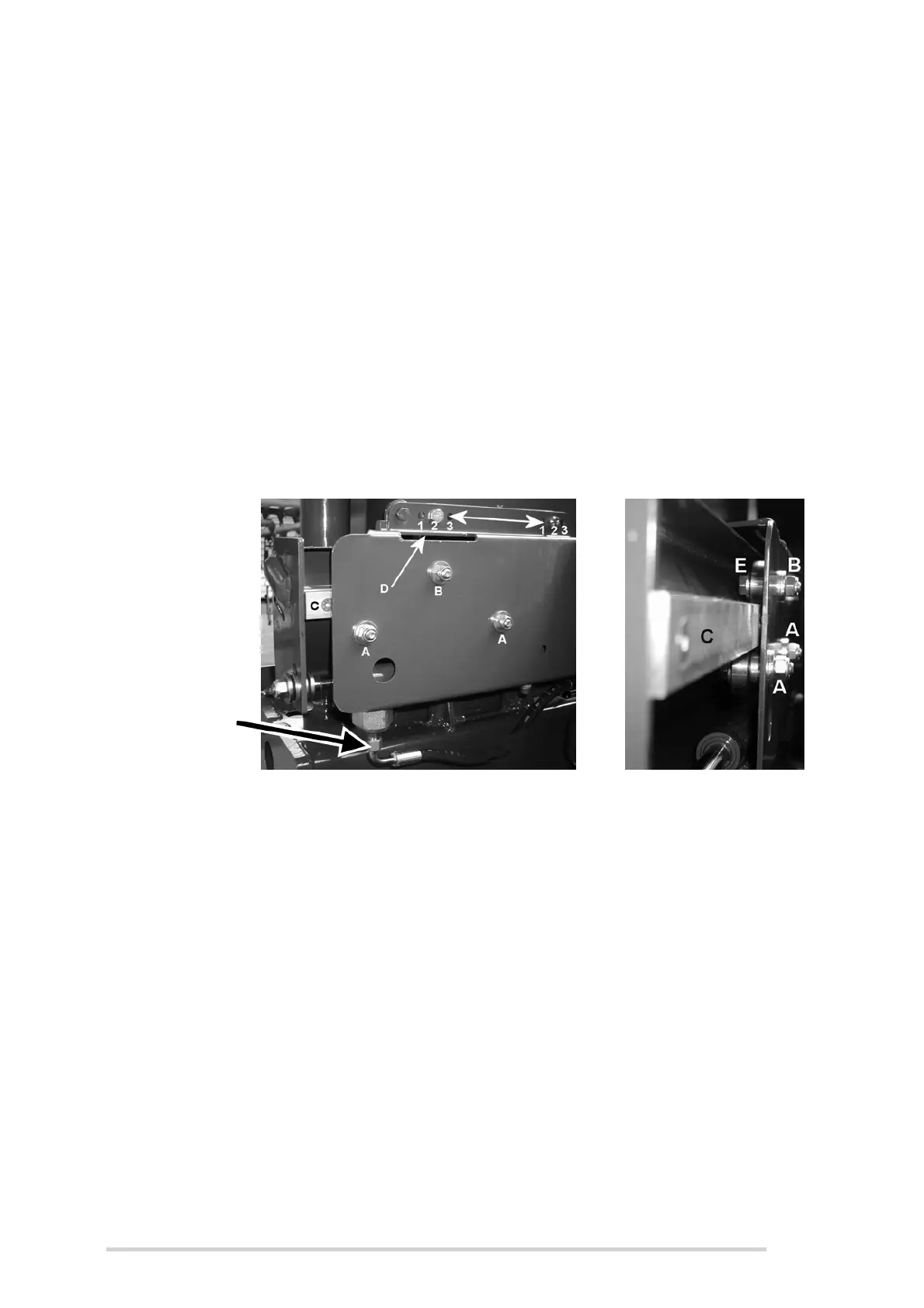
Cut and hold rail adjustment
After much use, the moving part of the cut and hold rail (C) may develop wear. In such
a case this may be adjusted, to ensure optimum working of the cut and hold. While
referring to Figure 8.l, adjust as follows:
1. Insert a 24 mm open ended spanner into slot (D) until it engages with the
hexagon on adjuster cam (E).
2. Loosen M12 nyloc nut (B) on adjuster slightly, just enough to be able to turn
adjuster (which works on a cam principle).
3. Turn adjuster (preferably clockwise from cam side E), with a 24 mm spanner,
until the resistance to turning increases greatly.
4. Hold resistive pressure on the adjuster cam (E) and tighten the M12 nyloc nut.
Figure 8.l - Cut and hold rail/horizontal position adjustment
Cut and hold horizontal position adjustment
The cut and hold assembly can be adjusted through three (3) different horizontal
positions, if desired. The factory set position is position 2 as shown in Figure 8.l. Ensure
that cut and hold assembly is safely secured (as assembly is quite heavy) before
attempting the following procedure:
1. Loosen and remove the four M12 x 40 mm bolts and 12 mm spacers and
carefully reposition bolts into the desired position i.e. 1, 2 or 3.
2. Place 12 mm spacers between cut and hold assembly and the main chassis,
then tighten M12 nyloc nuts to a torque value, as described in Section
“Tightening torque values” on page 108.
Accumulator
Pressure
Hose