15
qq
qq
Service manual for medifa 6000 mobile operating tables, version 2.0
height
tilt leg L
trend
reloc
leg R
back
X2
w b g
w b g
g b w
w b g
g b w
w b g g b w
X4
X6
X3 X5
X7
X1
leg R2 leg R1 leg L1 leg L2
y g w b w b y g
X12
X13 X14 X15
X23
X11
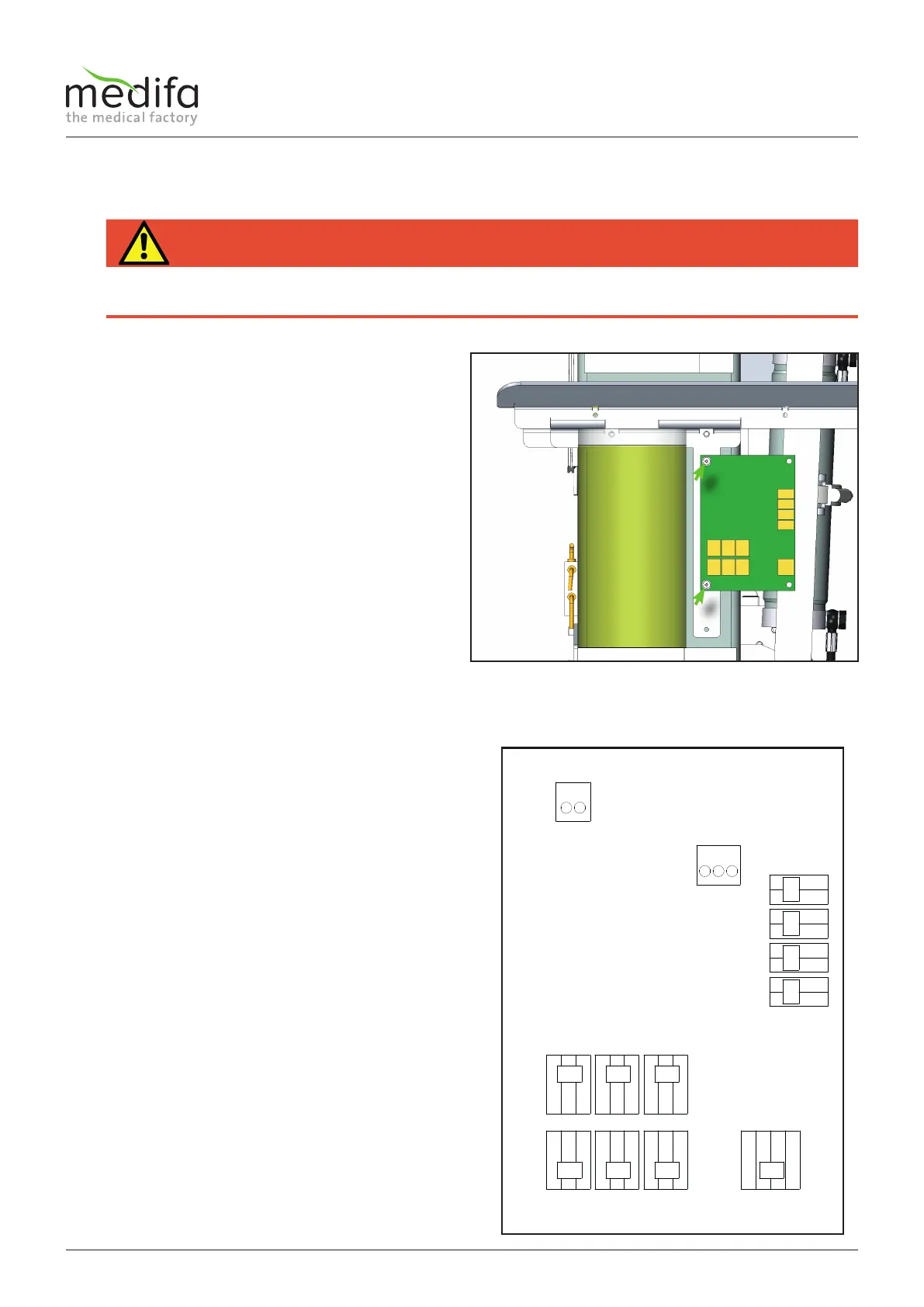
4.5 Replacing the distributor board
To remove the distributor board, the column cladding
must be removed (see chapter Removing the column
cladding).
Document the position of the cables before starting the
disassembly in order to be able to reassemble them later
in their original position.
First remove the electrical wiring. It proves helpful to
document the position of the wiring before dismantling
in order to be able to return it to its original position
afterwards. Then remove the two screws[1] to remove the
distributor board.
The assembly is carried out in the reverse order. Please
note that after the installation of the new distributor
board, the calibration program must be carried out (see
chapter Calibration).
The cable assignment can be taken from the cable diagram.
HAZARD
Danger of electric shock!
Before starting to replace the distributor board, you must put the operating table in a zero-voltage state, otherwise there is a
risk of electric shock.
Components column / top frame
Figure 14
x1 = back = displacement encoder system connection for lower
back plate
x2 = height = displacement encoder system connection for
height
x3 = trend = displacement encoder system connection for
Trendelenburg
x4 = tilt = displacement encoder system connection for lateral
x5 = reloc =displacement encoder system connection for
moveability
x6 = leg L = displacement encoder system connection for left
leg plate
x7 = leg R = displacement encoder system connection for right
leg plate
x12 = leg R1 = Switch in right leg plate receptacle, top
(for right split leg plate)
x13 = leg R2 = Switch in right leg plate receptacle, bottom
(for extension device)
x14 = leg L1 = Switch in left leg plate receptacle, top
(for left split leg plate)
x15 = leg L2 = Switch in left leg plate receptacle, bottom
(for extension device)
x23 = 24V connection (cable T04647 see cable diagram)
x11 = diagnostic connection (cable T04651 see cable diagram)
w= White
b = Brown
g = Green
y = Yellow
4.5.1 Cable assignment on the distributor board