16
ww
ww
qq
Service manual for medifa 6000 mobile operating tables, version 2.0
4.6 Replacing the distributor board
To replace the displacement encoder system of the
height adjustment, it is necessary to remove the column
cladding.
Please refer to the relevant chapters of this repair manual
for instructions!
After the column cladding has been removed, the bracket
must now be loosened by means of the two screws [1]
and carefully guided towards the potentiometer. When
installing the wire-rope pull potentiometer, also make
sure that the wire-rope does not snap upwards. This can
damage the wire-rope potentiometer.
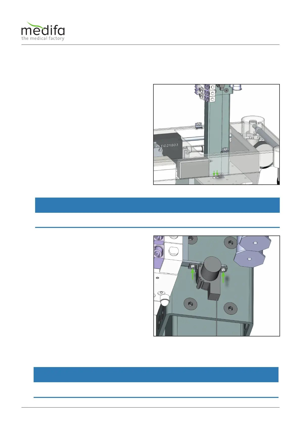
Now the two screws [2] can be removed from the
lifting column and the displacement encoder can be
dismounted. Then remove the wire-rope pull eyelet from
the mounting bracket.
In the next step the wiring must be traced back to the
connection point and removed from the distributor
board. Document the position of the cables and the cable
ties before starting the disassembly. When installing the
new cable, replace the cable ties in their original position.
Now the displacement encoder system can be replaced.
The installation of the new displacement encoder system
is carried out in the reverse order, kindly note that after
the installation of the new displacement encoder system,
the calibration programme must be carried out (see
chapter calibration).
The cable assignment can be taken from the cable
diagram.
4.6.1 Displacement encoder system connection of height adjustment
Components column / top frame
Figure 15
Figure 16
WARNING
When installing the wire-rope pull potentiometer, also make sure that the wire-rope does not snap upwards. This can dam-
age the wire-rope potentiometer.
WARNING
When installing the wire-rope pull potentiometer, also make sure that the wire-rope does not snap upwards. This can dam-
age the wire-rope potentiometer.