18
ww
rr
ee
qq
tt
Service manual for medifa 6000 mobile operating tables, version 2.0
4.6.3 Displacement encoder system of the Trendelenburg adjustment
To replace the displacement measuring system of the
Trendelenburg adjustment, the column cladding must be
removed.
You will find instructions for this in the corresponding
chapters of this manual!
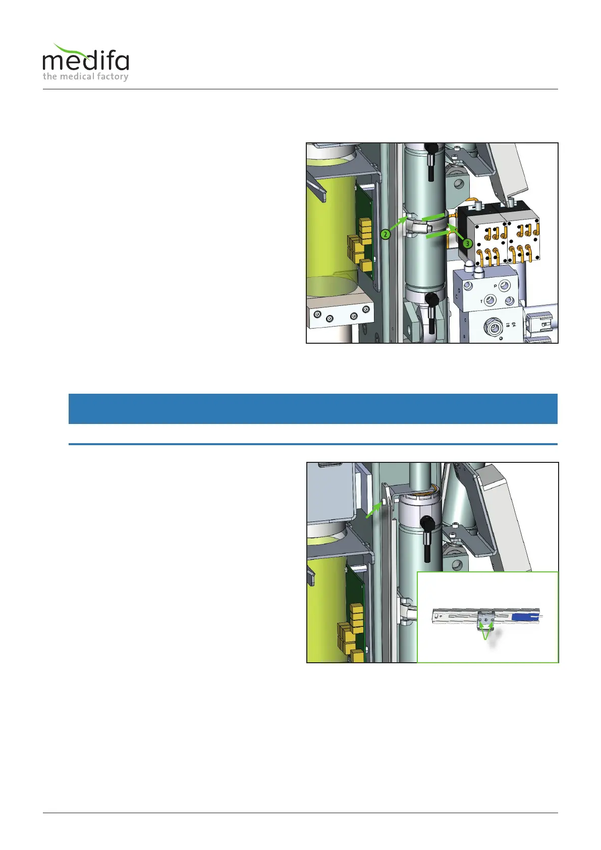
Before dismantling the displacement encoder system, it
is important to place a mark [1] on the cylinder so that
when the new displacement encoder is installed, the
position of the driver can be adjusted at the same height
to the cylinder.
After this, the driver [2] and the hose clamp [3] must be
removed.
WARNING
The driver must be installed in its original position during assembly.
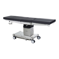
Now the screw connection [4] of the displacement
encoder system can be loosened and the system can be
placed on the base.
In the next step the wiring must be traced back to the
connection point and removed from the distributor
board. Document the position of the cables and the cable
ties before starting the disassembly. When installing the
new cable, replace the cable ties in their original position.
As a result, the driver holding plate must be removed
from the displacement encoder by loosening the screw
joint [5] and installed in the new displacement encoder
system.
Now the displacement encoder system can be replaced.
The assembly of the new displacement encoder system
is done in the reverse order. Please note that after the
installation of the new displacement encoder system, the
calibration programme must be carried out (see chapter
Calibration).
The cable assignment can be taken from the cable
diagram.
Figure 19
Figure 20
Components column / top frame