Do you have a question about the Medifa 6000 and is the answer not in the manual?
Records changes made to the service manual over different versions.
Details the product's classification and compliance with medical device directives.
Contact information and company specifics for the manufacturer.
Outlines copyright restrictions and intellectual property rights for the manual.
Guidelines and important considerations for trained service personnel.
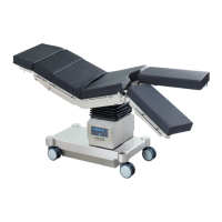
Explains the terminology and orientation for table alignment.
Explains hazard, warning, and caution symbols used in the manual for safety.
Lists essential preparatory actions before starting repair work, including safety precautions.
Step-by-step guide to detach the column cladding and keyboard board.
Instructions for detaching the bellows from the column cladding.
Procedure to inspect the hydraulic oil level in the operating table column.
Steps for detaching the padding plates from the table's upper frame.
Guide for replacing the main distributor board, including cable assignments.
Procedure for replacing the displacement encoder system for height adjustment.
Procedure for replacing the displacement encoder system for longitudinal movement.
Procedure for replacing the displacement encoder system for Trendelenburg adjustment.
Procedure for replacing the displacement encoder system for lateral adjustment.
Steps to replace the displacement encoder system for the back plate on model 601700.
Steps to replace the displacement encoder system for the back plate on models 601120 and 601820.
Steps to replace the displacement encoder system for the back plate on model 601920.
Procedure for replacing the displacement encoder system for leg plate adjustment on model 601920.
Procedure for replacing the displacement encoder system for the upper back plate.
Instructions for replacing the hydraulic unit of the operating table.
Steps to replace components related to rotary valves and hydraulic hoses.
Procedure to replace the main power input fuse for the operating table.
Steps to remove and install the power input module and its fuses.
Instructions for replacing the battery fuse in the operating table.
Guide for removing and installing the main control unit.
Procedure for replacing the external charge control unit.
Steps to remove and install the fifth wheel assembly.
Steps for safely removing and replacing the table's main batteries.
Procedure for removing and installing the twin swivel castor units.
Explains the purpose and process of calibrating the medifa 6000 operating table.
Details the step-by-step sequence and required angles for calibration.
Lists common problems, probable causes, and remedies for basic faults.
Lists common problems, probable causes, and remedies for advanced faults.
Lists common problems, probable causes, and remedies for functional failures.
Lists and illustrates spare parts for the base of the operating table.
Lists and illustrates spare parts for the column of the operating table.
Lists spare parts for the manual switch unit.
Lists and illustrates spare parts for the top frame of model 601120.
Lists and illustrates spare parts for the top frame of model 601700.
Lists and illustrates spare parts for the top frame of model 601820.
Lists and illustrates spare parts for the top frame of model 601920.
Lists and illustrates spare parts for the head plate assembly.
Lists and illustrates spare parts for the leg plates assembly.
Lists and illustrates spare parts for the leg plates assembly.
Lists and illustrates spare parts for the upper back plate assembly.
Detailed hydraulic schematic for model 601120 of the operating table.
Detailed hydraulic schematic for models 601700 and 601820.
Detailed hydraulic schematic for model 601920 of the operating table.
Illustrates the electrical connections and wiring paths within the operating table.
Lists visual and functional checks for the manual switch and column components.
Lists visual and functional checks for the chassis and base of the operating table.
Lists visual and functional checks for the top frame components.
Outlines required safety tests and their parameters as per VDE 0751 standard.
| Brand | Medifa |
|---|---|
| Model | 6000 |
| Category | Medical Equipment |
| Language | English |