30
ww
ww
rr
rr
rr
rr
rr
rr
rr
qq
qq
ee
ee
Service manual for medifa 6000 mobile operating tables, version 2.0
Components column / top frame
4.8 Replacing the batteries
To replace the rotary valves of the table, first remove the
cladding. Please refer to the relevant chapters of this
manual for instructions!
First the connecting cables of the two adjustment motors
on the rotary valve must be removed.
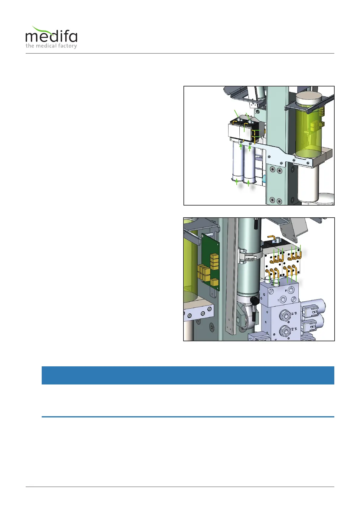
To do this, pull down the two transparent protective
tubes [1] on the rotary valve.
Proceed carefully so as not to damage the cables!
If the protective tubes are off, the red and the blue
connecting cable can now be disconnected from the
adjustment motor. Document the laying of the cables to
bring them back to their original position when installing
them. Repeat this procedure for the second motor as well.
Next, the entire valve block itself can be unscrewed from
the table. To do this, remove the two screws [2] on the
bracket.
After unscrewing the valve block from the table, the two
forked photoelectric sensors [3] on the top of the valve
block should be removed.
To do this, loosen the two plastic screws of the respective
forked photoelectric sensor.
Now that all electrical connections on the valve block
have been removed, the valve block should hang
exclusively on the hydraulic hoses [4].
Before you can now start removing these hoses [4], the
entire upper frame of the table must be supported so
that the pressure is taken off the cylinders. To do this,
clamp squared timbers or similar under the lying surface.
WARNING
All cylinders of the table which are under pressure should be retracted as far as possible. It is important that the height ad-
justment is completely retracted. In addition, the entire lying surface of the table must be supported against sagging before
you remove the hydraulic hoses [4] from the valve block, otherwise oil can escape from the hoses under high pressure and
the lying surface would sag!
After the table top is well supported, you can start to detach the hoses from the block on both the front and back sides. To do
this, simply remove the screw of the holding plate directly next to the hydraulic hose [4]. Document the position of the hoses
[4], using the hydraulic diagram, before you start dismantling. This will later make it easier to fit the hoses to the new valve
block [2].
Figure 46
Figure 47