60
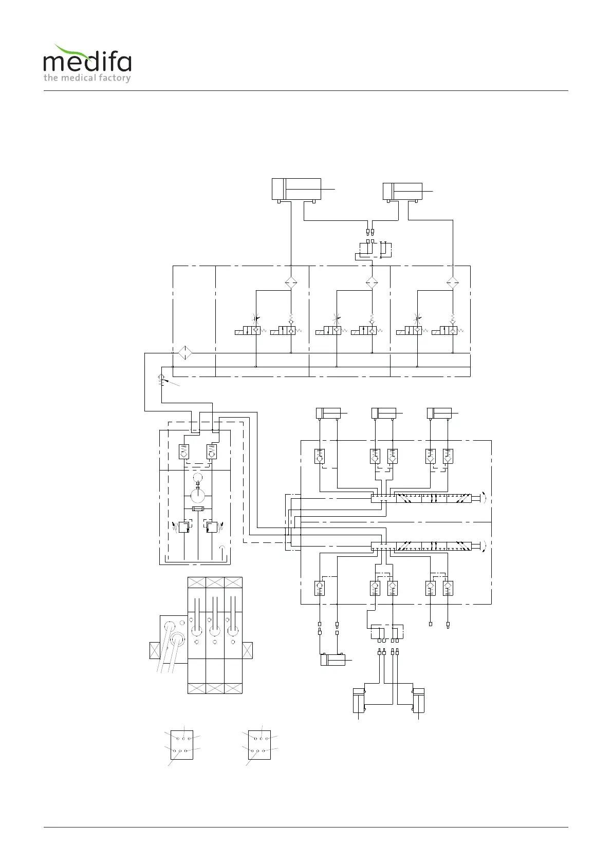
Rechter Rücken-Zylinder
Linker Rücken-Zylinder
1a 1b 2a 2b 3a 3b
Anschlußblock
P
T
Rechter
Beinplatten-Zylinder II
Verteilerplatte
Magnetventil-Kette
Rückschlagventil in Hohlschraube
Linker
Beinplatten-Zylinder I
600 01
L
Rotationsventil II (4x90°)
A
B
Hub-Zylinder Lateral-ZylinderTrendelenburg-Zylinder
Rotationsventil I (4x90°)
600 02
600 03
M
T
A
Hydraulik-Aggregat
Verteilerplatte
Anschlüsse
Rückseite
Rotationsventil I
B
Brems-Zylinder
600 04
600 05
600 06
600 07
600 08 600 09
600 10
600 11
600 12
600 13
600 14
600 15
120 01 120 02
920 10
920 11
920 12
920 13
920 01
920 02
920 03
920 04
920 05
920 06
920 07
600 04
600 05
600 06
600 08
600 09
600 07
600 10
600 11
600 12
600 14
600 15
600 13
T
P
1
2
3
4
7
1a 2a 3a
1b 2b 3b
Anschlüsse
Rückseite
Rotationsventil II
Anschlüsse
Magnetventile
Service manual for medifa 6000 mobile operating tables, version 2.0
Hydraulic diagram
9.3 Hydraulic diagram 601920