17
ww
qq
rr
tt
ee
Service manual for medifa 6000 mobile operating tables, version 2.0
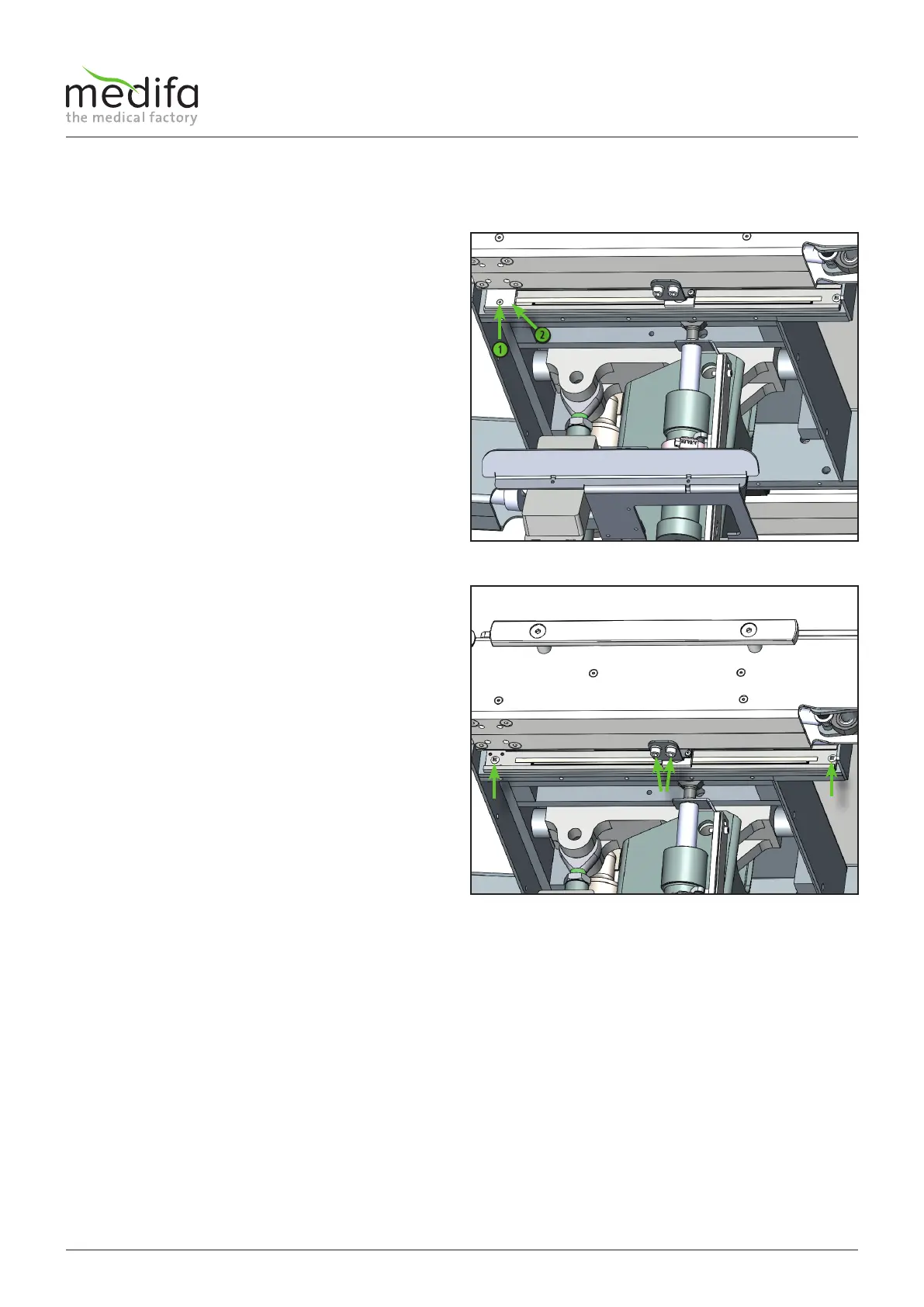
First loosen the screw [1] at the end of the
displacement encoder system and disassemble the
plastic cover [2].
Now remove the screws [3] for fastening the tab for the
displacement encoder system for the displacement under
the right pelvic rail.
Now the screw [4] can be removed by exposing the
contacts and then the screw[5] can be removed.
In the next step the wiring must be traced back to the
connection point and removed from the distributor
board. Document the position of the cables and the cable
ties before starting the disassembly. When installing the
new cable, replace the cable ties in their original position.
Now the displacement encoder system can be replaced.
The installation of the new displacement encoder system
is carried out in the reverse order, kindly note that after
the installation of the new displacement encoder system,
the calibration programme must be carried out (see
chapter calibration).
The cable assignment can be taken from the cable
diagram.
Figure 17
Figure 18
4.6.2 Displacement encoder system of longitudinal displacement
Components column / top frame