21
ee
qq
Service manual for medifa 6000 mobile operating tables, version 2.0
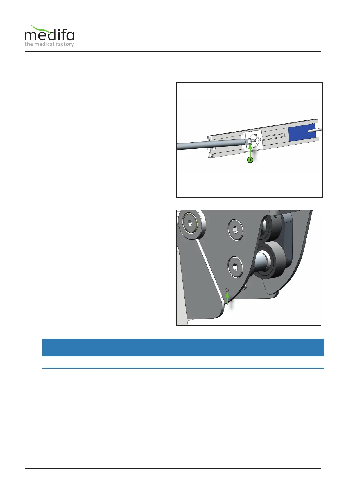
Then remove the driver with the guide rod and mount it
on the new displacement encoder system. To remove it,
you only need to remove the screw [3].
Now the displacement encoder system can be replaced.
The assembly of the new displacement encoder system
is done in the reverse order. Please note that after the
installation of the new displacement encoder system, the
calibration programme must be carried out (see chapter
Calibration).
The cable assignment can be taken from the cable
diagram.
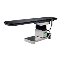
When installing the screws [3] and [1], use a screw
locking adhesive to protect them against loosening.
Recommended adhesive: Loxeal 55-03
WARNING
When reinserting the driver guide on the backrest rail, make sure that the screw [1] does not protrude from the hole.
Components column / top frame
Figure 25
Figure 26