26
rr
tt
yy
uu
Service manual for medifa 6000 mobile operating tables, version 2.0
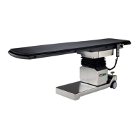
Then remove the driver with the guide rod and mount it
on the new displacement encoder system. To remove it,
you only need to remove the screw [7].
Now the displacement encoder system can be replaced.
The assembly of the new displacement encoder system
is done in the reverse order. Please note that after the
installation of the new displacement encoder system, the
calibration programme must be carried out (see chapter
Calibration).
The cable assignment can be taken from the cable
diagram.
When installing the screw [7], use a screw locking
adhesive to protect it against loosening. Recommended
adhesive: Loxeal 55-03
Components column / top frame
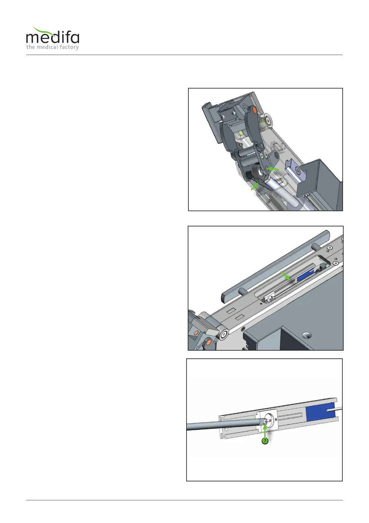
Now the bolt [4] can be pushed out to the right so that
the adjustment bar [5] is free of the bolt [4].
Then remove the displacement encoder system [6] from
the upper pelvic rail opening.
In the next step the wiring must be traced back to the
connection point and removed from the distributor
board. Document the position of the cables and the cable
ties before starting the disassembly. When installing the
new cable, replace the cable ties in their original position.
Figure 37
Figure 38
Figure 39