28
ee
Service manual for medifa 6000 mobile operating tables, version 2.0
Components column / top frame
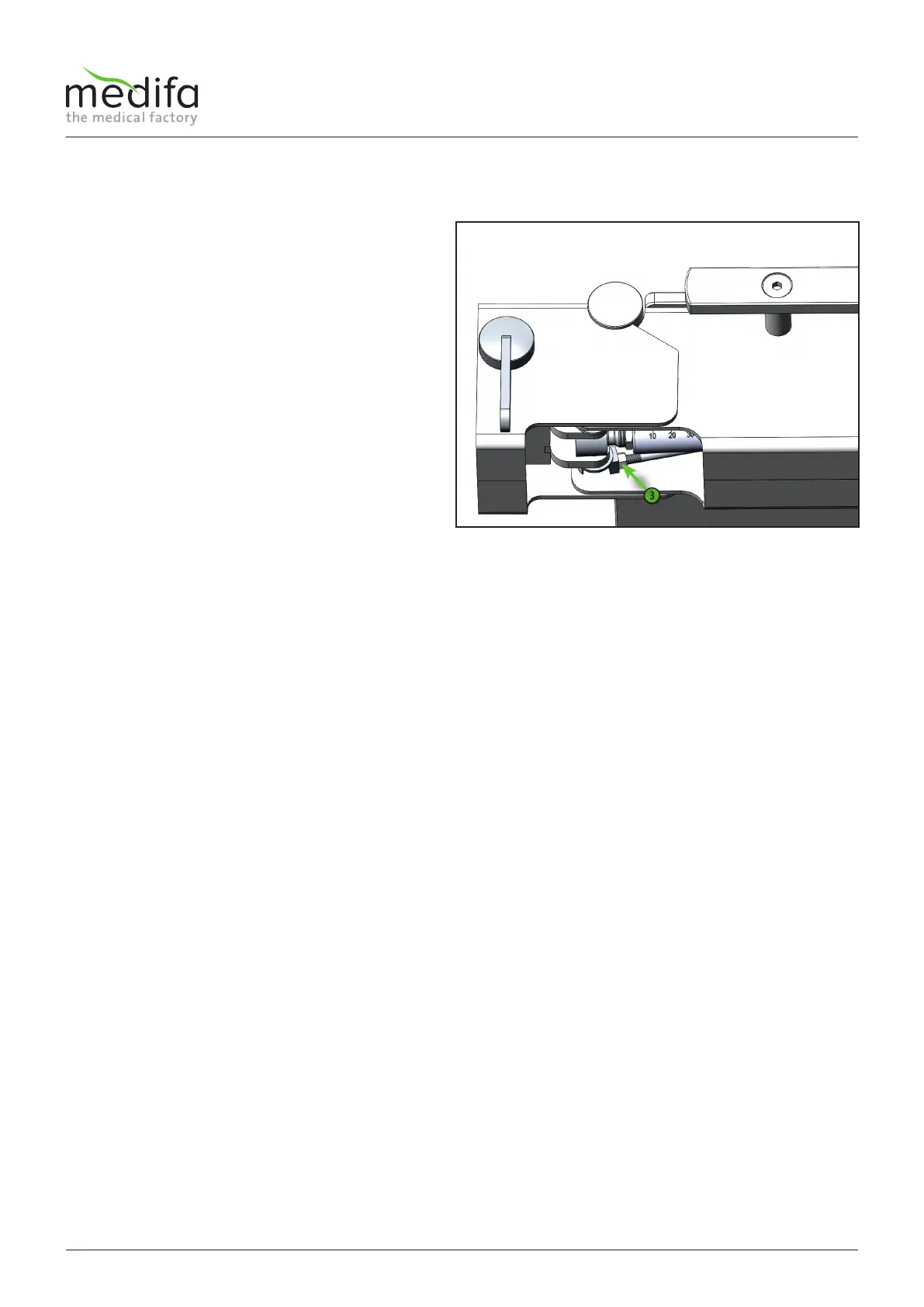
Now the displacement encoder system can be replaced.
The assembly of the new displacement encoder system
is done in the reverse order. The cable assignment can be
taken from the cable diagram.
Please note that after the installation of the new
displacement encoder system, the calibration has to be
carried out manually. This is done by adjusting the nut[3]
on the extending rod. If the extending rod is adjusted
longer, the zero position is shifted to positive. If the
extending rod is set shorter, the zero position is shifted to
negative.
Adjust the zero angle slightly to the positive.
Figure 43