56
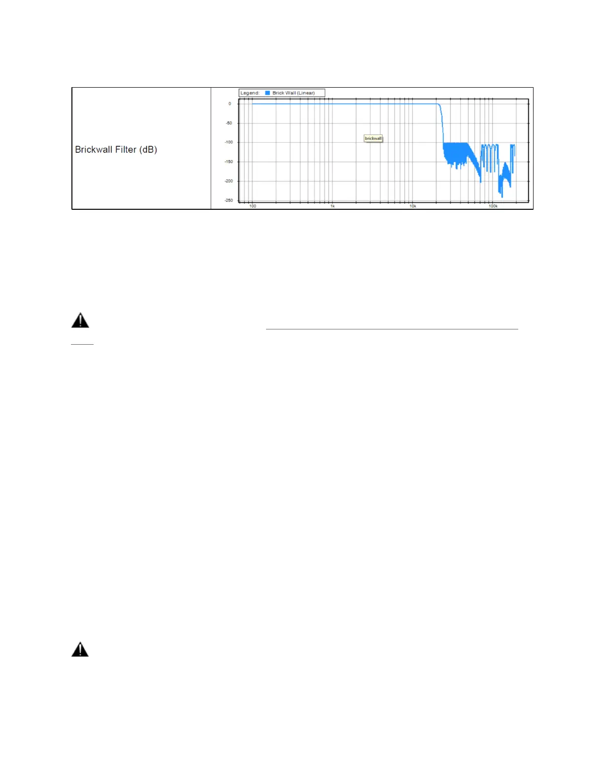
Brickwall: Ensures rejection of more than -100dB at Nyquist (0.50 x FS). Latency of 35 samples
XLR 1/2: Line output level of the physical XLR outputs 1 and 2 located at the back to the Anubis
Max Output Level: +18dBu or +24dBu
Channel 1: Definable individual Trim and Polarity settings
Channel 2: Definable individual Trim and Polarity settings
Warning: Please refer to the section on How to connect a balanced line output to an unbalanced
input regarding Max Output Level limitation.
JACK 3/4: Physical TRS jack outputs 3 and 4 located at the back to the Anubis
Same parameters as above (XLR 1-2)
HEADPHONE 1: Headphone set 1 located at the front Anubis left side
Max Output Level: +9dBu or +18dBu
Channel 1: Definable individual Trim and Polarity settings
Channel 2: Definable individual Trim and Polarity settings
HEADPHONE 2: Headphone set 2 located at the front right side of the Anubis
Same parameters as above (Headphones 1).
The Anubis digital to analog converters are designed to drive high or low impedance headphones
at high levels with significant audio output Power undistorted.
User should be attentive to the impedance of the headphones being used and set the Anubis
Max Output level accordingly.
Warning: It is not recommended for headphones with an impedance below 200 Ohms to select an
Output Level of +18dBu. As a preventive measure, a warning message will be displayed each time a
user changes the Output Level of the Headphones from +9dBu to +18dBu.