Contents
780/781 pH/Ion Meter, Manual
V
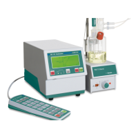
Fig. 1: 781 pH/Ion Meter connected to 801Magnetic Stirrer .................................................... 1
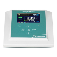
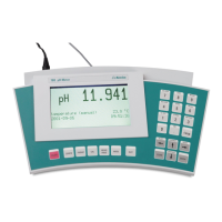
Fig. 2: Front view of the 780 pH Meter or 781 pH/Ion Meter .................................................... 3
Fig. 3: Rear view of the 780 pH Meter or 781 pH/Ion Meter ..................................................... 4
Fig. 4: Possible arrangements for mounting the base plate .................................................... 8
Fig. 5: Attaching the support rod and base plate..................................................................... 8
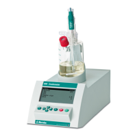
Fig. 6: Ready-mounted pH/ISE measuring system .................................................................. 9
Fig. 7: 780 pH Meter / 781 pH/Ion Meter – 801 Magnetic stirrer .............................................. 9
Fig. 8: 780 pH Meter / 781 pH/Ion Meter – 802 Rod stirrer .................................................... 10
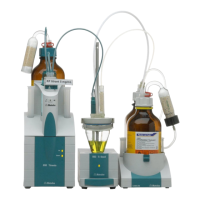
Fig. 9: 781 pH/Ion Meter – Dosimat Plus ................................................................................ 11
Fig. 10: 781 pH/Ion Meter – Dosimat Plus – Sample changer ............................................... 12
Fig. 11: 780 pH Meter / 781 pH/Ion Meter – Printer ............................................................... 13
Fig. 12: Connecting sensors ................................................................................................... 16
Fig. 13: Remote outputs in limit monitoring .......................................................................... 110
Fig. 14: Diagram showing changes in potential during an electrode test ........................... 129
Fig. 15: Theoretical U/pH relationship ................................................................................ 138
Fig. 16: 3-Point pH calibration .............................................................................................. 139
Fig. 17: Connections of the optional 6.2148.010 Remote box ............................................. 156
Fig. 18: Pin occupancy at remote interface .......................................................................... 156