Page 60 Electrical installation
Product Manual / Mounting Instructions „Servo drives ARS 2320 FS, ARS 2340 FS and ARS 2360W FS“ Version 1.0
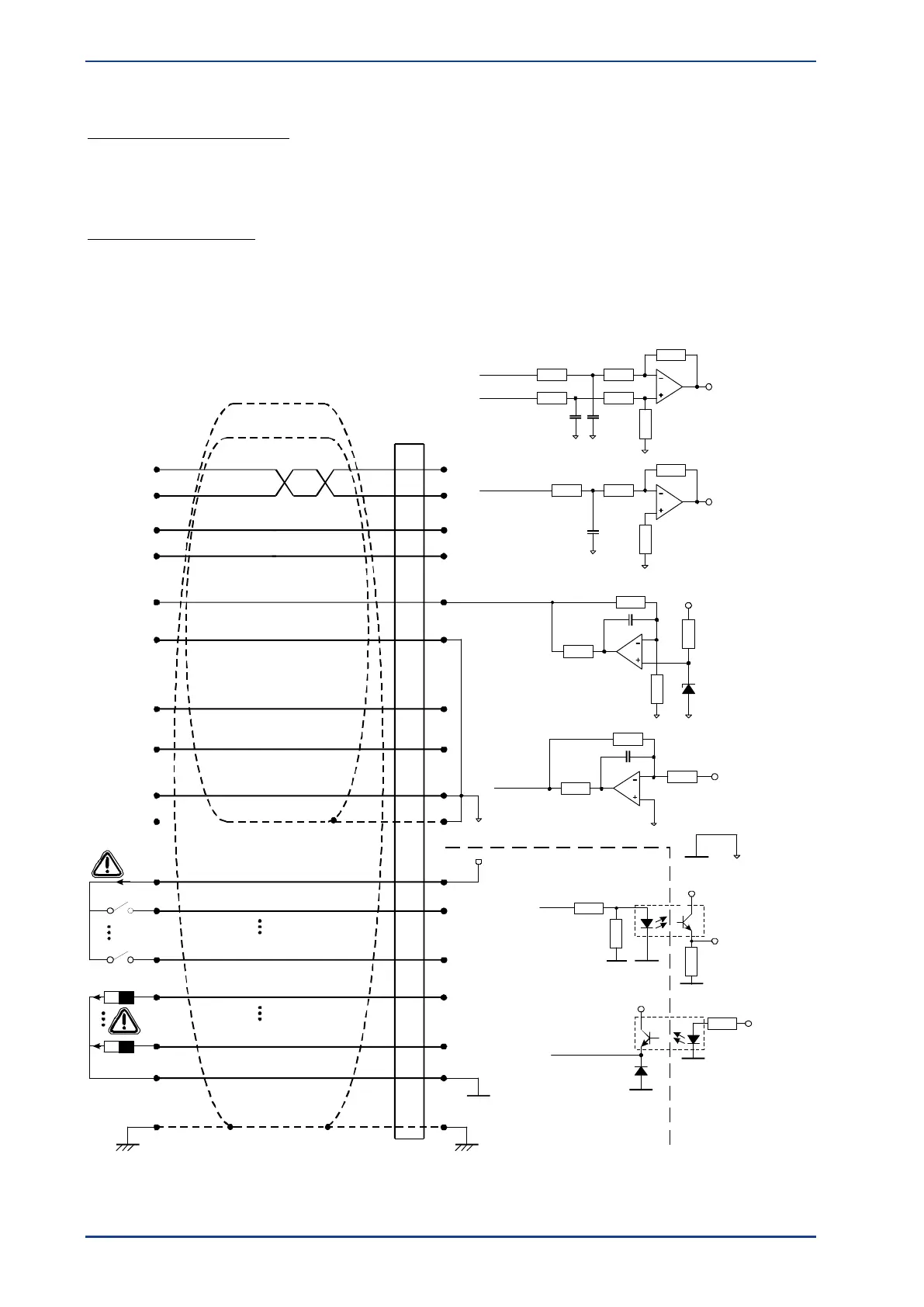
The servo drives ARS 2300 FS features two potential ranges:
Analogue inputs and outputs:
All of the analogue inputs and outputs refer to AGND. AGND is internally connected to GND, the
reference potential for the control module with C and AD converters in the servo drive. This potential
range is electrically isolated from the 24 V range and from the DC bus circuit.
24 V inputs and outputs:
These signals refer to the 24 V supply voltage of the ARS 2300 FS servo drive, which is supplied via
[X9B]. They are separated from the reference potential of the control module by way of optocouplers.
24
11
19
6
18
14
1
5
14
17
4
16
3
15
2
13
DOUT 3
DIN
9
DOUT 0
DIN
0
GND24
+ 24 VDC
+VREF
AMON 0
AIN 1
AIN 0
Pin Nr.
X1
AMON 1
AIN 2
#AIN
0
AGND
AGND
DOUT x
GND24
+ 24 VDC
+ 24 VDC
GND
GND24
PEPE
100 mA
max !
100 mA
max !
Connector housing
+VREF
AIN 0
#AIN 0
AGND
AIN 1 / AIN 2
AGND
+ 15 V
AGND
AGND
AMON x
AGND
GND AGND
DIN x
GND24
GND
Control system ARS 2300 FS
Figure 24: Basic circuit diagram of connector [X1]
 Loading...

