Electrical installation Page 55
Product Manual / Mounting Instructions „Servo drives ARS 2320 FS, ARS 2340 FS and ARS 2360W FS“ Version 1.0
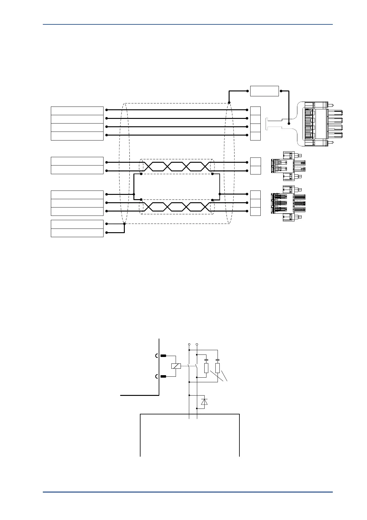
8.4 Motor [X6, X6A, X6B]
The motor is connected to the terminals U,V,W via motor cable to [X6].
The motor temperature sensor is connected to terminals MT+ and MT-, if it is lead into one cable together
with the motor phases. If a temperature sensor (e.g. KTY81) is used in the motor, it is connected via the
encoder cable to [X2A] or [X2B].
Figure 22: Motor connection [X6]
Terminals BR+ and BR- can be used to connect a holding brake of the motor. The holding brake is
supplied with power via the power supply of the servo drive. Please note the maximum output current that
is provided by the ARS 2300 FS servo drive. It may be necessary to connect a relay between the device
and the holding brake.
ARS 2300 FS
BR-
BR+
2
1
Power supply
unit + 24 V
Power supply
unit GND
Resistor and capacitor
for spark suppression
Motor with
holding brake
Holding brake + 24 V
Holding brake GND
Flyback diode
Figure 23: Connecting a holding brake with a high current demand (> 2 A) to the device
Motor Phase W resp. 3
BR-
BR+
Motor Phase U resp. 1
Motor Phase V resp. 2
PE (Motor)
Motor connectors
1
4
1
2
2
3
Connector housing
Motor housing
Cable shield
3
1
2
PE (optional)
MT+
MT-
[X6.]
[X6B]
[X6A]
 Loading...

