Electrical installation Page 71
Product Manual / Mounting Instructions „Servo drives ARS 2320 FS, ARS 2340 FS and ARS 2360W FS“ Version 1.0
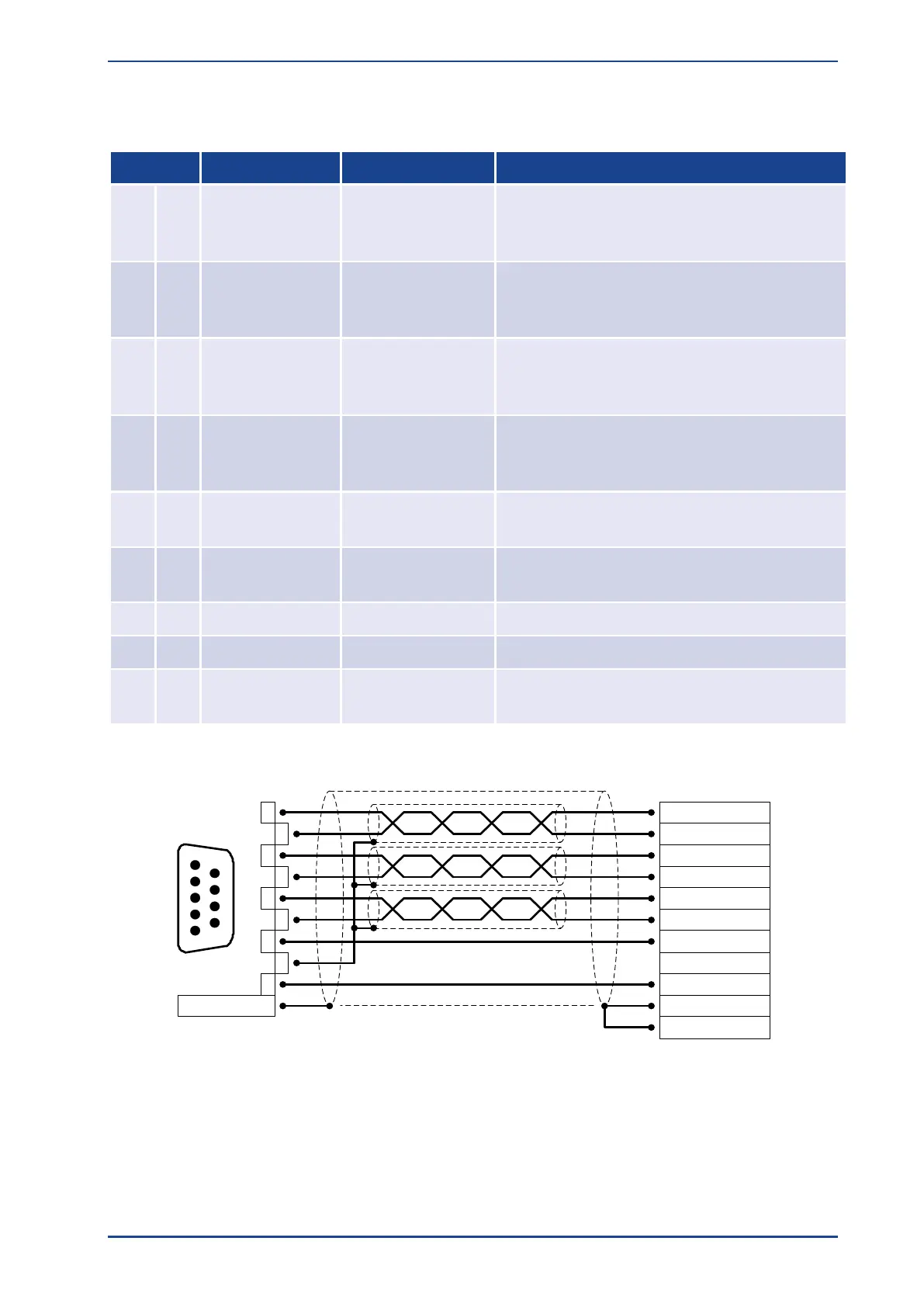
8.10 Incremental Encoder Input [X10]
Pin assignment X10 Incremental Encoder Input
Incremental encoder signal A /
Stepper motor signal CLK
positive polarity as per RS422
Incremental encoder signal A# /
Stepper motor signal CLK
negative polarity as per RS422
Incremental encoder signal B /
Stepper motor signal DIR
positive polarity as per RS422
Incremental encoder signal B# /
Stepper motor signal DIR
negative polarity as per RS422
Incremental encoder index pulse N
positive polarity as per RS422
Incremental encoder index pulse N#
negative polarity as per RS422
Reference GND for encoder
Shield for the connection cable
Auxiliary supply (short circuit-proof), load with
100mA maximum
2
3
4
5
6
7
8
1
9
Connector
housing
1
5
9
6
Cable shield
(optional)
B# / DIR#
B / DIR
N
A / CLK
N#
GND
VCC
A# / CLK#
Incremental encoder
(e.g. ROD 426)
D-SUB connector
at X10
Incremental encoder input
Male
Connector housing
Figure 33: Pin assignment: Incremental encoder input [X10]
Input [X10] can be used to process incremental encoder signals and pulse direction signals like the ones
generated by the control boards for stepper motors.
The input amplifier at the signal input is designed to process differential signals in accordance with the
RS422 interface standard. Processing of other signals and levels (e.g. 5 V single-ended or 24 V
HTL
of a
PLC) may also be possible. Please contact your sales partner.
 Loading...

