Page 52 Electrical installation
Product Manual / Mounting Instructions „Servo drives ARS 2320 FS, ARS 2340 FS and ARS 2360W FS“ Version 1.0
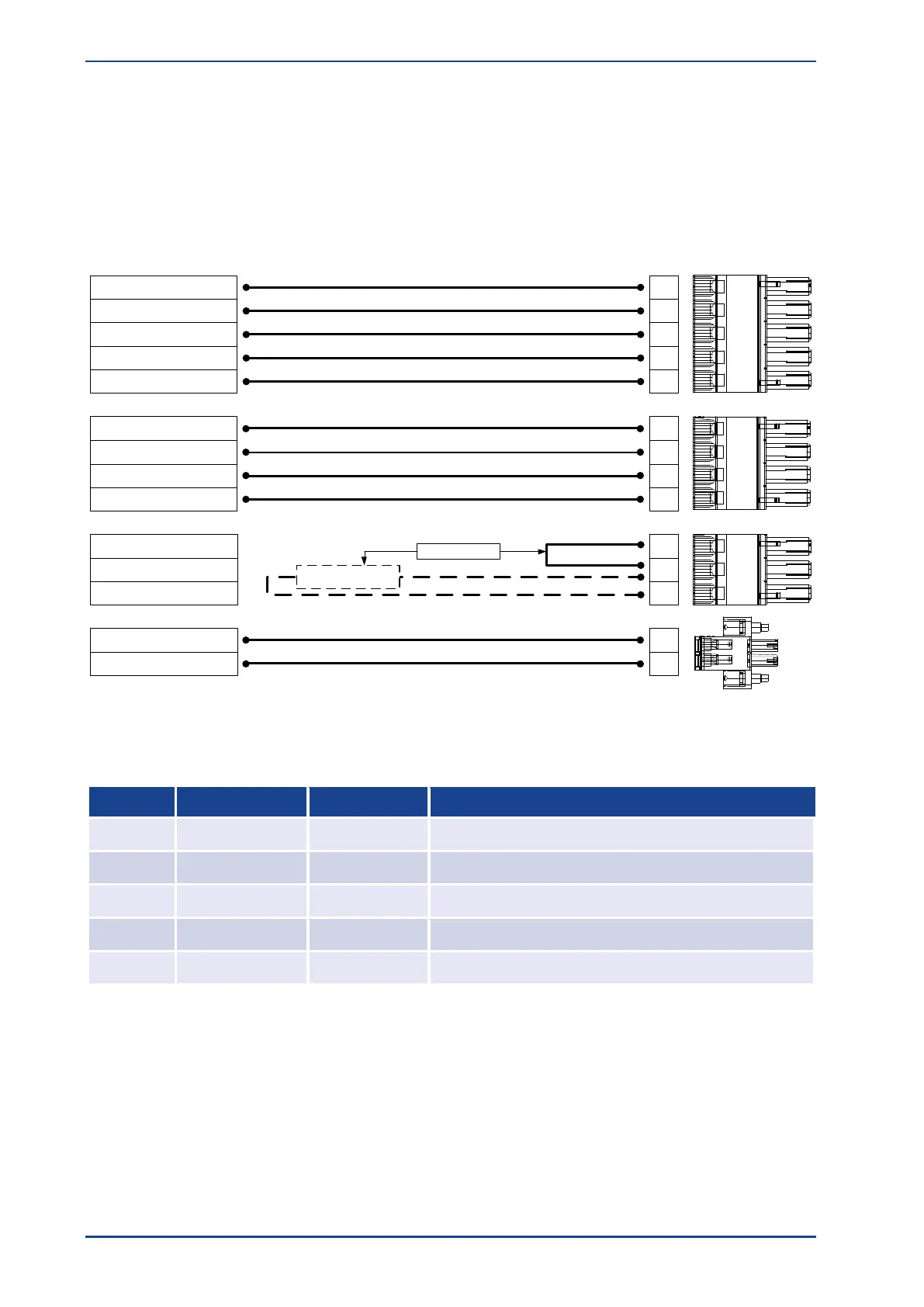
8.3 Power Supply [X9, X9A, X9B, X9C]
The operation of the Servo drive ARS 2300 FS requires a 24V supply source for the electronics, which is
connected to the terminals +24V and GND. The connection to the supply for the power output stage is
made to terminals L1, L2 and L3 for AC supply.
The ARS 2300 FS servo drive has an internal brake chopper and braking resistor. For more braking
power, an external braking resistor can be connected to the [X9A] pin-and-socket connector.
1
4
1
3
2
5
2
3
Power connectors
ZK+
PE
PE
L3
ZK-
ZK+
L1
L2
ZK- 4
External
brake resistor
alternative !
[X9.]
1
2
3
1
2
R-INT
R-EXT
R-CH
24V
GND
[X9C]
[X9A]
[X9B]
Figure 21: Supply connection [X9]
Connection of mains ground conductor PE
1
Connection of mains ground conductor PE
1
One PE connection on X9 is sufficient
Additional PE connection on the mounting plate / cold plate:
It is necessary to make an additional PE connection on the cold plate (M4 screw) with the same cross
section like the mains supply, see picture in chapter 7.
 Loading...

