Electrical installation Page 53
Product Manual / Mounting Instructions „Servo drives ARS 2320 FS, ARS 2340 FS and ARS 2360W FS“ Version 1.0
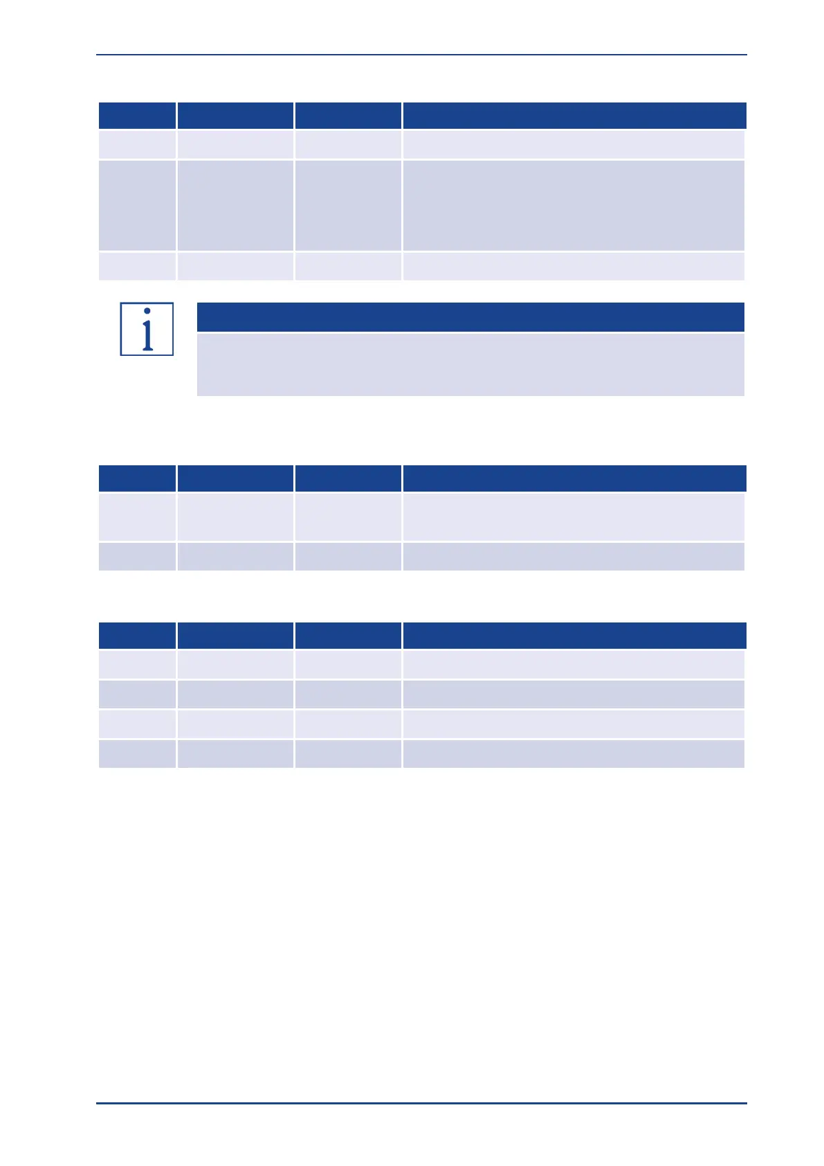
Pin assignment X9A Brake Resistor
Internal braking resistor
Brake chopper connection for external braking
resistor against BR-EXT
Brake chopper connection (wire jumper) for internal
braking resistor against BR-INT
Internal braking resistor
If no external braking resistor is used, a bridge has to be installed between PIN1 and
PIN2, so that the DC bus precharge, when the mains power supply is “ON”, and the
DC bus rapid discharge can function properly!
Pin assignment X9B 24V Supply
Reference potential for the 24VDC supply and the
PLC
24VDC supply for control section
Pin assignment X9C DC BUS
 Loading...

