XTreme-EMS Operating Manual Page 68
10.3.1 Connecting the RDAC-XF / RDAC-XG / RDAC-CAN to the Xtreme-EMS
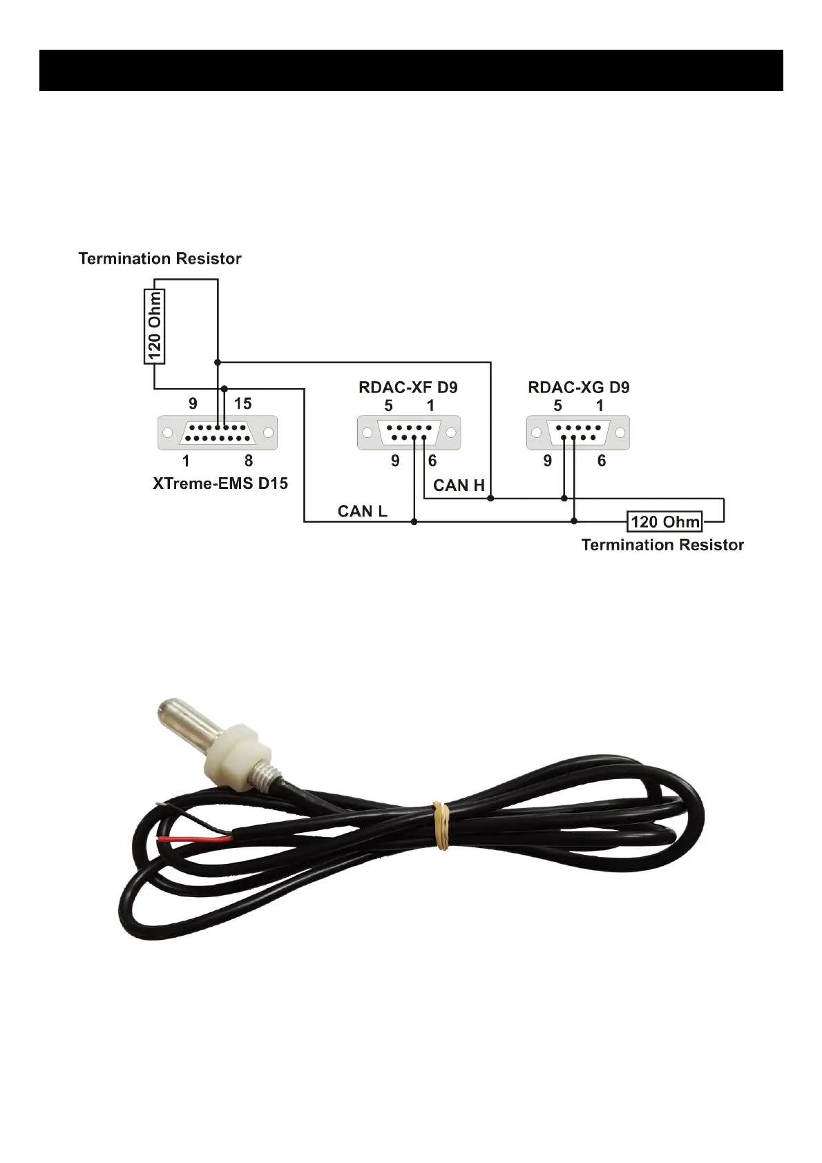
Observe the polarity of the two CAN wires. One of the lines is called “CAN L” and the other “CAN H”. It is recommended
that a twisted pair wire is used for this connection using two wire colors for ease of identification. The CAN bus must be
terminated at each end with a 120 ohm resistor. Connections from equipment into the CAN bus (other than the ends)
must only use short stubs into the bus (maximum length of a stub should not exceed 20cm if possible). It is okay to use
only a single resistor of value 120 ohms if the total length of the CAN bus is not more than two meters (6 feet).
10.4 OAT Probe
Connect the OAT probe red wire to the Xtreme EMS OAT Probe input (Green wire) and the OAT Probe black or green
wire to ground.