XTreme-EMS Operating Manual Page 45
Menu options for all sender types
LABEL:
Enter a label to suit your temperature channel so you can identify it easily.
TEMPERATURE UNIT:
Select whether you want the temperature to be displayed in degrees Celcius (ºC) or in degrees Fahrenheit (ºF).
DISPLAY MAX:
Select the maximum temperature that you want the bargraph to show. This can give you increased display resolution.
DISPLAY MIN:
Select the minimum temperature that you want the bargraph to show. This can give you increased display resolution.
HIGH ALARM:
This enables or disables the temperature high alarm.
HIGH ALARM:
Enter the temperature threshold for when the high alarm must be activated. Any temperature above this value will activate
the alarm.
HIGH CAUTION:
Enter the temperature value for the high caution. This is the lower value of the upper yellow band.
LOW CAUTION:
Enter the temperature value for the low caution. This is the upper value of the lower yellow band.
LOW ALARM:
This enables or disables the temperature low alarm.
LOW ALARM:
Enter the temperature threshold for when the low alarm must be activated. Any temperature below this value will activate
the alarm.
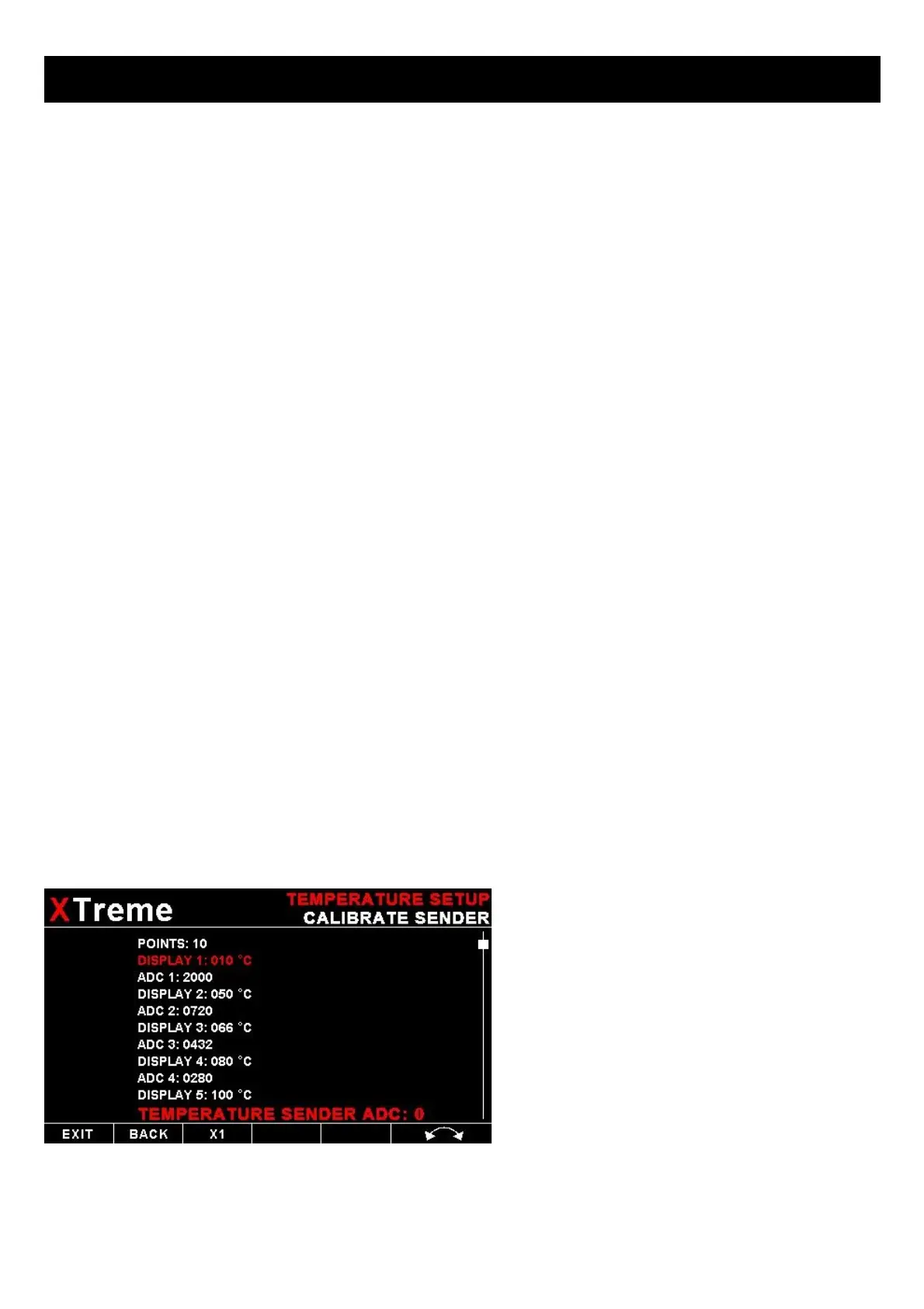
4.3.9 Calibrating the user defined pressure and Temperature Senders
1. Enter the number of points that you want to
calibrate.
2. Enter the display reading that you want to
show when the sender is at that actual display
reading.
3. Enter the ADC (analog to digital converter)
reading that corresponds to this display reading.
The ADC reading is shown at the bottom of the
display if you are applying the actual
stimulus from the temperature or pressure
sender. You can also manually enter this value
if the ADC value is known or pre-calculated.
4. Continue entering display and ADC values
until all the points have been entered.
5. Verify the above calibration by checking the
temperature/pressure display versus the actual
applied sender stimulus.