EasyManuals Logo

MICRO-EPSILON scanCONTROL 30 Series User Manual

MICRO-EPSILON scanCONTROL 30 Series
62 pages
To Next Page IconTo Next Page
To Previous Page IconTo Previous Page
Page #22 background imageLoading...
Page #22 background image
Page 22
Installation and Mounting
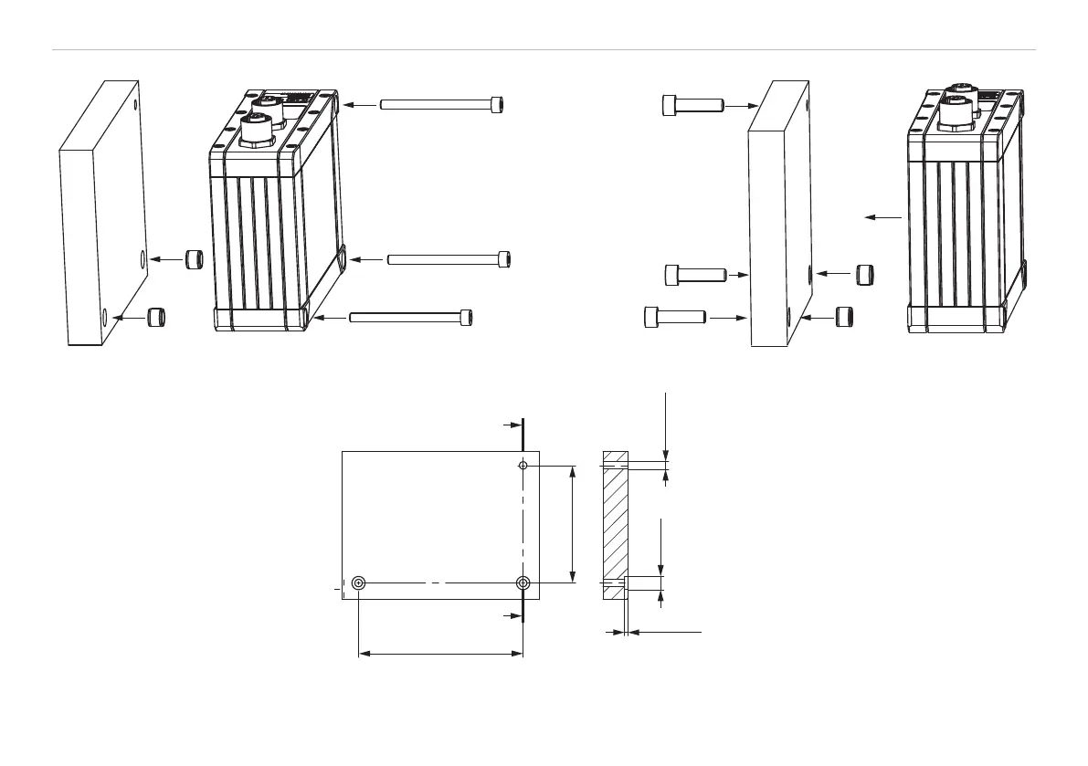
scanCONTROL 30xx
(2)
(1)
(1) Screw M4
(2) Centering element
(2)
(1)
(1) Screw M5
(2) Centering element
Fig. 3 Mounting example with bolt connection Fig. 4 Mounting example with direct fastening
Bolt connection:
- 3 threaded holes (M4)
with centering element:
- additionally 2 cylindrical counter-
bores 8H7 depth 1.8 - 2 mm
100 ±0.2
71.5 ±0.2
3 x
ø4.5
3 x M4
ø8 H7
1.9 ±0.1
Direct fastening:
- 3 bores ø 5.5
with centering element:
- additionally 2 cylindrical counterbores
8H7 depth 1.8 - 2 mm
Fig. 5 Dimensional drawing mounting bores,
dimensions in mm, not to scale

Table of Contents

Questions and Answers:

Question and Answer IconNeed help?

Do you have a question about the MICRO-EPSILON scanCONTROL 30 Series and is the answer not in the manual?

MICRO-EPSILON scanCONTROL 30 Series Specifications

General IconGeneral
BrandMICRO-EPSILON
ModelscanCONTROL 30 Series
CategoryScanner
LanguageEnglish