Page 33
Installation and Mounting
scanCONTROL 30xx
5.2.5 Ethernet Connection
Connector “Ethernet“, see Fig. 10.
The Ethernet connection is the standard connection to the PC.
The sensor supports the transmission with 100 Mbit and 1 Gbit.
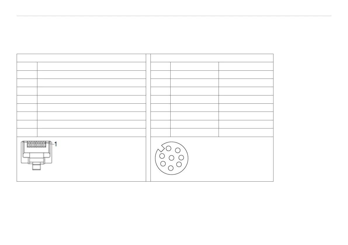
RJ45 connector 8-pin. screw connector (sensor side)
Pin no. Color of stranded hook-up wire SCR3000A-x Pin no. 100BaseTX 1000BaseT
1 White (orange) 5 Tx+ D1+
2 Orange 6 Tx- D1-
3 White (green) 8 Rx+ D2+
4 Blue 1 D3+
5 White (blue) 2 D3-
6 Green 7 Rx- D2-
7 White (brown) 3 D4+
8 Brown 4 D4-
View on pin side of male cable
connector
2
3
4
5
6
7
8
1
View on solder side
(cable) of screw connector
(A-coded)
Fig. 16 Pin assignment Ethernet connection
 Loading...