Page 49
2D/3D Output Unit
scanCONTROL 30xx
Mount the components of a 2D/3D Output Unit on a top hat rail (TS35) in the described order.
Without using a top hat rail a robust installation cannot be guaranteed. Ensure that each module is locked securely on the top hat rail.
Terminate the bus with the bus termination, see Fig. 26.
For a description of the individual components of the 2D/3D Output Unit, please refer to Chap. 7.4, the respective datasheets and the
manuals for scanCONTROL Configurations Tools.
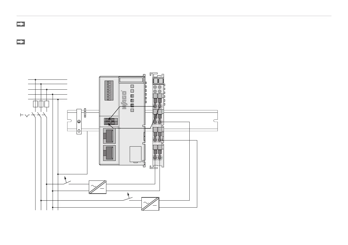
7.2 Connect the Power Supply
OU-Filter module
OU Fieldbus Coupler
+
+
-
13
14
C
D
B
A
750-626
+
+ Ñ
-
-
253-057
LINK
ACT
MS
I/O
ETHERNET
NS
87654321
NO
LINK
ACT
1
2
X
1
X
2
8
1
ON
24V
X3
0V
0: WBM
255: DHCP
System supply
Field supply
230 V
24 V
230 V
24 V
L1
L2
L3
N
PE
Digital output
modules need a field
supply of 5 VDC or
24 VDC depending
on the module type.
Fig. 27 Separated power units for system and field supply (Ethernet)
After mounting of the modules, the required wiring has to be installed.
 Loading...