Page 31
Installation and Mounting
scanCONTROL 30xx
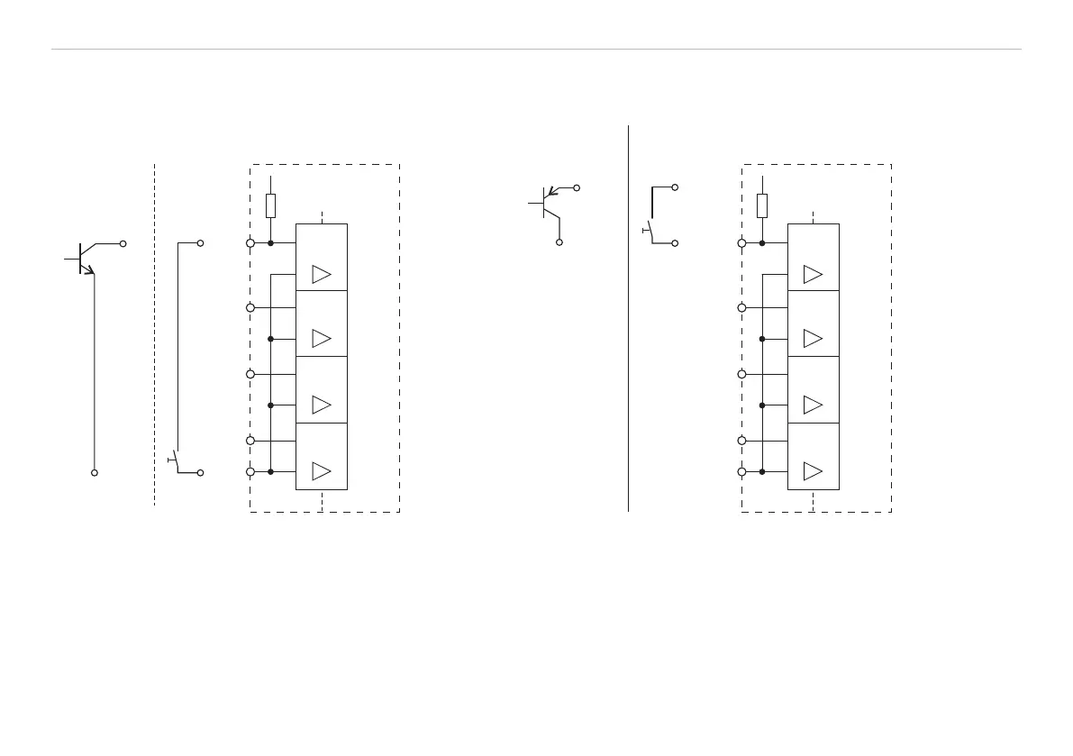
5.2.4 Switching Inputs
Connector multifunction socket, see Fig. 10, pin assignment, see Fig. 11.
7
4
GND
scanCONTROL
30xx
Type 1
Transistor
Type 2
Switch
+U
i
10 kOhm
NPN
8
4
6
In 1
In 2
In 3
GND
7
5
In 4
Isolation
4
24V
5V
Type1
Transistor
Type 2
Switch
PNP
24V
5V
4
scanCONTROL
30xx
GND
10 kOhm
8
4
6
In 1
In 2
In 3
GND
7
5
In 4
Isolation
Fig. 14 Pull up Fig. 15 Pull down
The switching inputs In1 up to In4 can be used for triggering or for connecting an encoder. All switching inputs are identical. The used
circuits have an internal electrical isolation. The inputs are galvanically isolated from the GND and Laser on/off .
All switching inputs have one ground connection (GND-In), which has to be connected with the external ground (synchronization/trig-
ger source or another device).
 Loading...