Page 30
Installation and Mounting
scanCONTROL 30xx
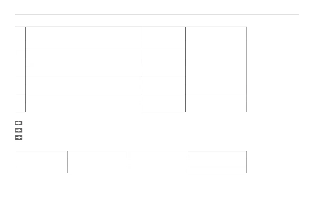
The multifunction socket can be used with either of the following configurations:
Configuration Direction Standard setting for
terminating resistor R
T
0 Half-duplex, serial communication with 115200 Baud input/output On
1 Half-duplex, serial communication with 57600 Baud input/output
2 Half-duplex, serial communication with 38400 Baud input/output
3 Half-duplex, serial communication with 19200 Baud input/output
4 Half-duplex, serial communication with 9600 Baud input/output
5 External trigger input input On
6 External trigger output output Off
7 CMM trigger output output Off
Synchronizing several sensors with each other:
Connect the output RS422+ (Pin 12) of sensor 1 with the input RS422+ (Pin 12) of sensor 2.
Connect the output RS422- (Pin 11) of sensor 1 with the input RS422- (Pin 11) of sensor 2.
Also connect both the GND-RS422 (Pin 10) of the sensors to each other.
Software settings:
Setting Sensor 1
Sensor 2
1
Other sensors
RS422 mode External trigger output External trigger input External trigger input
RS422 termination Off On Off
Fig. 13 External synchronization settings
The sensor 1 then synchronizes the sensor 2 and further sensors as master.
1) The terminating resistor is activated (On) at the sensor that is physically furthest away from sensor 1 (Master).
 Loading...