Page 27
Installation and Mounting
scanCONTROL 30xx
5.2 Connections
5.2.1 General
1 2
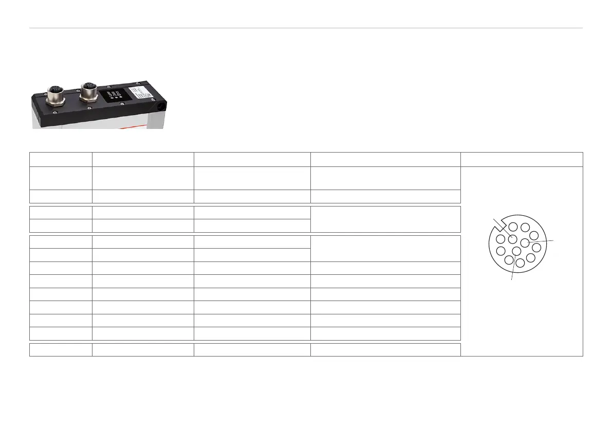
1 Multifunction socket (Power supply, IO)
2 Ethernet socket
Fig. 10 Output sockets arrangement
Designation Sensor connector Pin Cable color PCR3000-x Notes Connection view
+Ub 9 Red
+ 11 V - 30 V DC
(rated value 24 V); max. 5 W
2
3
4
5
6
7
8
9
1
10
12
12-pin screw connector,
view on solder side (cable)
GND 2 Blue 0 V
+Laser on/off 3 White
Available with SI option
-Laser on/off 1 Brown
RS422 12 Red-blue
RS422
input or output
/RS422 11 Gray-pink
GND RS422 10 Purple Ground connection RS422
In1 4 Green Switching input In1
In2 6 Yellow Switching input In2
In3 8 Gray Switching input In3
In4 5 Pink Switching input In4
GND-In 7 Black Ground connection In
Screen Housing Black Not electrically connected to GND
Fig. 11 Assignment of the multifunction socket on scanCONTROL 30xx
GND: Galvanically isolated from In1 ... 4, RS422, laser on/off
laser on/off: input galvanically isolated from GND, In1 ... 4, RS422
In1 ... 4, RS422: inputs galvanically isolated from GND and laser on/off
 Loading...