Page 41
Operation of the Sensor with a PC
scanCONTROL 30xx
6.4.2 Calibration
The calibration of the sensor is performed using the complete sensor matrix and is independent from the selected measuring field.
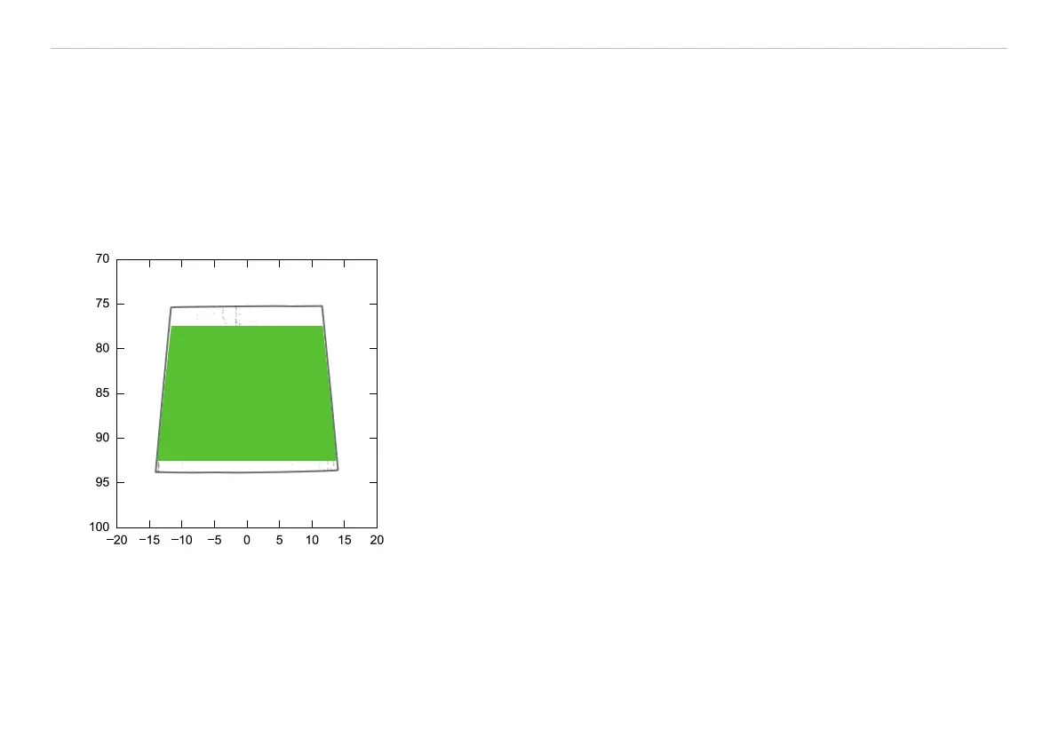
The trapeze form of the measuring field is produced from the projection onto the sensor matrix. The standard measuring range is
framed in the center.
A calibration final inspection is enclosed for each sensor. Three diagrams for the linearity measurement which are briefly explained in
the report are included in the calibration final inspection. The key diagram in the calibration final inspection is shown again below, see
Fig. 20.
Points with deviation > 0.01 mm
Distance z [mm]
Position x [mm]
Fig. 20 Linearity deviation, example of an scanCONTROL 30xx-25
The black points show the places where the measurement error exceeds the linearity limit of 0.01 mm
(depending on sensor model). The measurement error increases at both ends of the depth range and particularly in the remote cor-
ners. These areas should therefore be avoided for the measurement.
 Loading...