Page 21
Installation and Mounting
scanCONTROL 30xx
5. Installation and Mounting
5.1 Attachment and Mounting
- using 2 or 3 screws M5, screwed directly
- using 2 or 3 screws M4, screwed pushed through
Depending on the installation position, it is recommended to define the sensor position using centering elements and fitting bores.
The cylindrical counterbore ø8H7 is intended for the position-defining centering elements. This allows for the sensor to be mounted in
a reproducible and exchangeable way.
The mounting dimensions refer to the dimensional drawings.
Pay attention to careful handling during mounting and operation.
The bearing surfaces surrounding the fastening holes (through-holes) are slightly raised. Mount the sensor only
to the existing holes on a flat surface. Clamps of any kind are not permitted. Do not exceed torques. If possible,
mount the sensor with side A as bearing surface.
> Damage to or destruction of the sensor, inaccurate, erroneous measuring values.
The laser beam must strike the target surface at right angles. Otherwise, inaccurate measurements cannot be excluded.
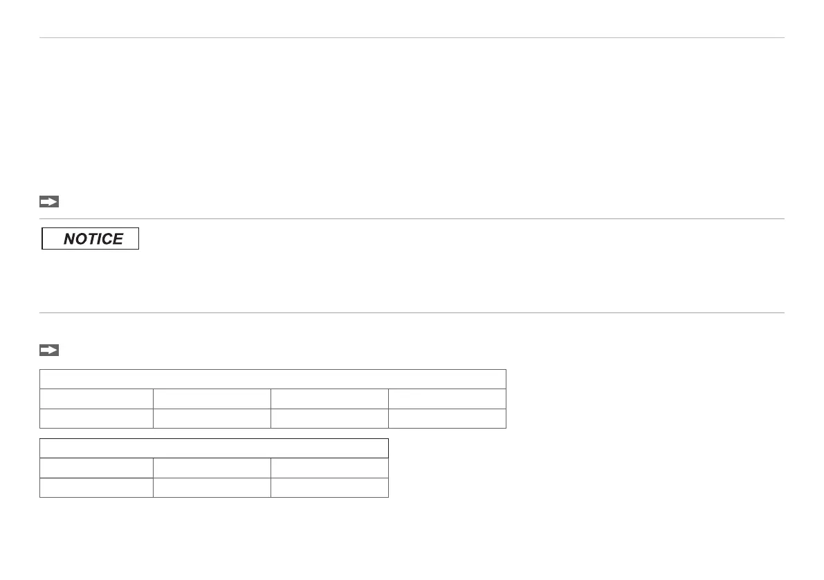
Mount the sensor by means of screws type M5 or by means of through bores for M4.
Bolt connection
Through length Screw Washer Torque
40 mm M4 x ISO 4762-A2 A 4,3 ISO 7089-A2 1.9 Nm
Direct fastening
Screw depth Screw Torque
min 14 mm M5 x ISO 4762-A2 2.5 Nm
Fig. 2 Mounting conditions
 Loading...