Workstation 4 Setup Guide B-9
Connector and Cable Diagrams
Hook-up Cables
LCD Customer Display Cables
The new LCD based Customer Display is accompanied by three new cable
assemblies. The function of each cable is detailed in the following pages.
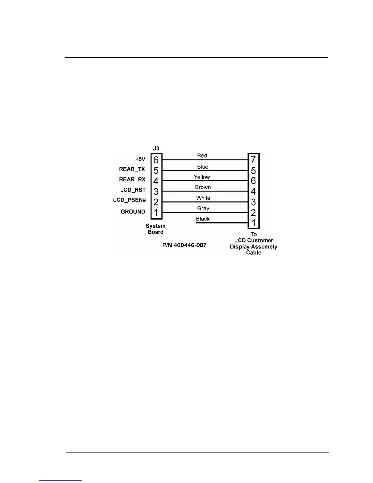
System Board Integrated Cable
This cable is attached to System Board connector J1 and pre-installed in WS4s
built after May 2004. A diagram is shown in Figure B-13. This cable mates
with the cable from the LCD customer display assembly, shown in Figure
B-14.
Figure B-13: System Board to Rear LCD Customer Display
LCD Customer Display Assembly Interface Cable
The LCD Customer Display Assembly includes the LCD Display Housing,
which in turn consists of LCD Panel, Interface Board, mounting bracket and
interface cable. A diagram of this interface cable is shown in Figure B-14. The
only difference between the Rear and Pole versions of the LCD customer
display housing is the mounting hinge.
When the LCD customer display is attached directly to the rear of the
workstation, this cable plugs into the system board cable shown in Figure
B-13.
When the LCD customer display assembly is mounted on the pole, this cable
attaches to the cable shown in Figure B-15, below.