3-10 Workstation 4 Setup Guide
Installing and Operating the Workstation 4
Operation
Operation
This section presents operational procedures for the Workstation 4 including
how to use the power button to transition the unit between the NOPOWER, ON
and SUSPEND power states.
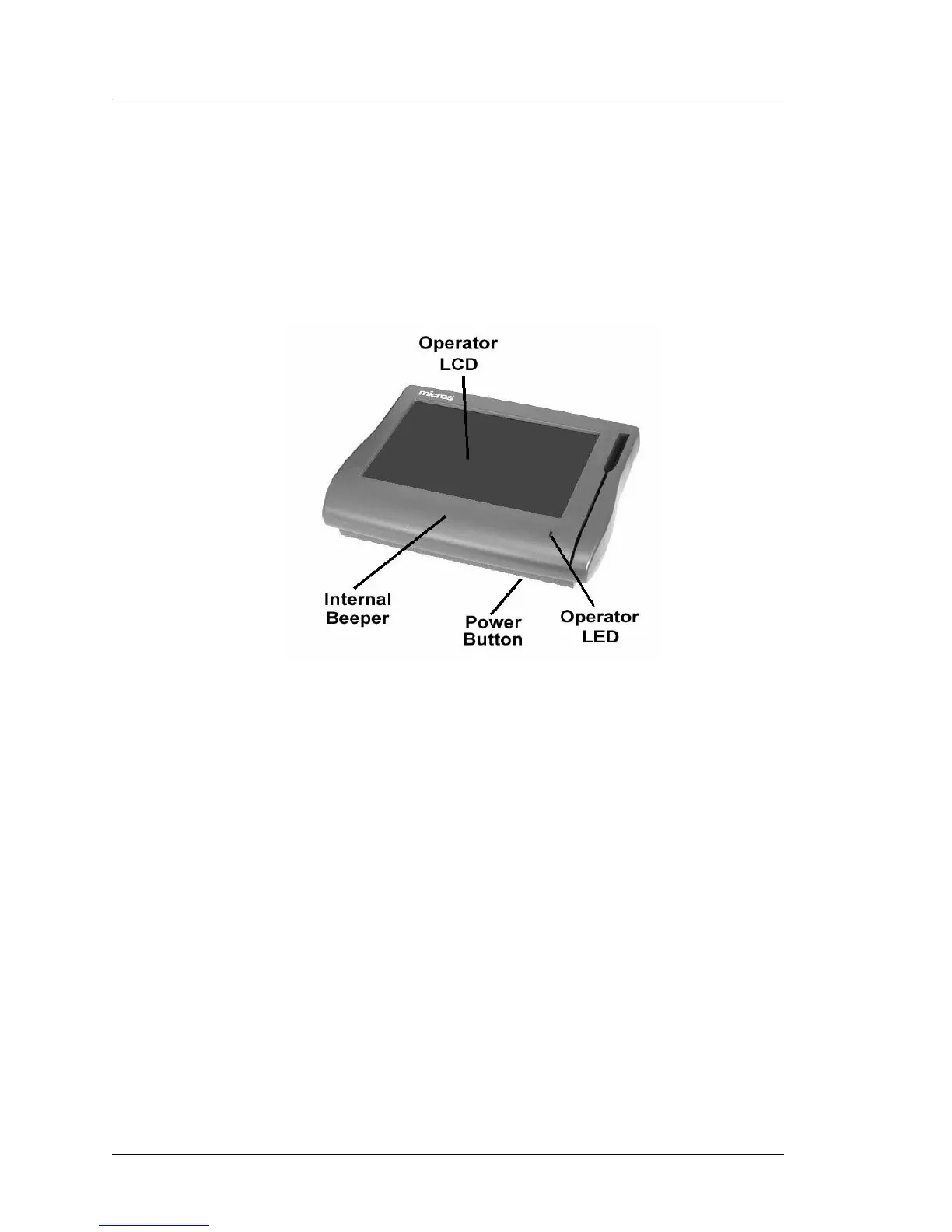
Figure 3-4 points out the location of the Workstation 4 Power Switch, Operator
LED, Magnetic Card Reader, and the Operator LCD.
Figure 3-4: Workstation 4 Operator Features
Operator LCD
The Operator LCD is an 12.1” Active Matrix Display with a resolution of
800x600. The 5-wire resistive touchscreen glass is positioned over the LCD.
Power Switch
The power switch is used by the operator to transition the Workstation 4
between the various power management states.
Operator LED
The Operator LED displays the current power state and is capable of
displaying three colors - Green, Amber, and Red. In addition, each color can be
solid, or blink at one of three rates .25Hz, 1Hz, or 4Hz.
Internal Beeper
A Beeper is located inside the workstation to provide information to the
operator about the Workstation’s status.