Workstation 4 Setup Guide 2-21
What’s Inside?
Hardware Updates
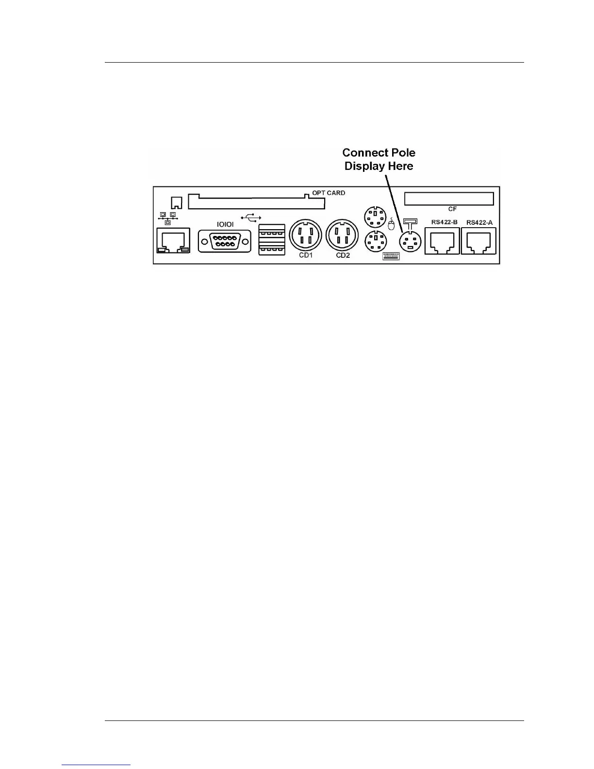
3. Figure 2-19 points out the location of the Pole Display connector.
Power-off the WS4 and attach the keyed 4-Pin DIN connector on the cable
to the Customer Display Connector on the workstation IO Panel.
Figure 2-19: Connecting the Pole Display to the WS4 IO Panel
4. Refer to the software requirements section below.
Software Configuration
The WinCE image on a WS4 configured to run the e7 POS Application
includes the necessary drivers to support the Rear/Pole LCD Customer
Display. However the majority of WS4s currently in the field (as of September
2004) are running the GR1.0 or GR1.1 software platform. If connected to a
WS4 running GR1.0 or GR1.1, the LCD customer display will not function.
An upgrade to GR1.2 or later is required to support the 2x20 VFD emulation
mode. In addition, the graphics features of the display are not yet supported by
POS Applications such as RES or L&E, however, the 2x20 VFD emulation is
supported.
Instructions for upgrading the WS4 to the GR1.2 software platform can be
found in FB004-001. This document and the GR1.2 software platform files can
be found in the hardware support section at www.micros.com.