21
www.roadwidener.com
Model SP-8 & 10
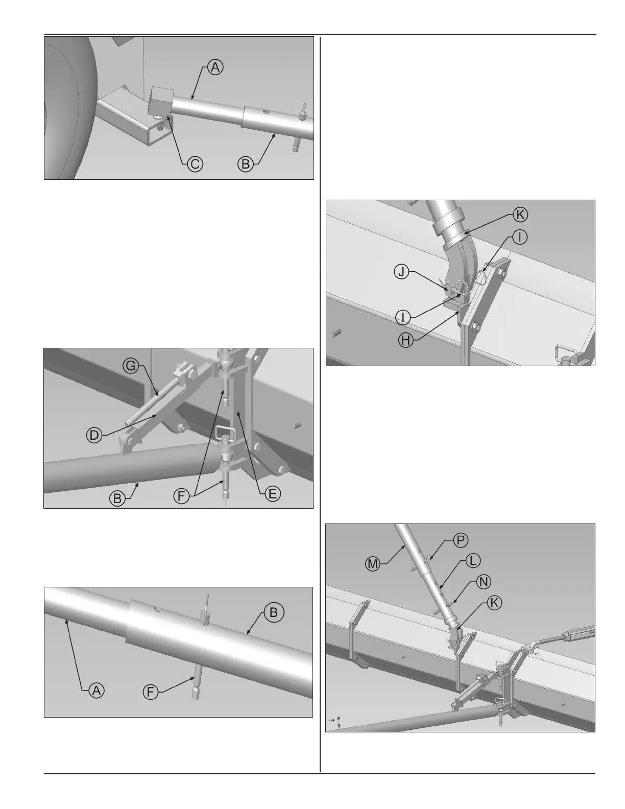
5. Insert inner push tube (A) into outer push tube (B).
6. Install push tube (A) over ball hitch on machine.
Install pins (C) to fasten push tube to ball hitch
7. On blade, align outer push tube (B) and stabilizer
(D) in mounting Bracket (E) holes and insert Hitch
pin (F).
8. Press reworked cam (G) to lock stabilizer.
9. Keeping blade angle as close as possible to 45
degrees, nd a conguration where one hole each
on inner push tube (A) and outer push tube (B) are
in-line and insert hitch pin (F) through them.
Note: Depending on material, a greater blade angle
may be needed to ll entire spread width. Narrow
spread widths do not require as much blade angle.
10. Slope mount (H) should be mounted at approximately
2/3rd of blade length. To change location of slope
mount (H), lower blade down to ground by toggling
grade & slope switches on operator console.
11. Pull out cotter pins (I) and remove hinge pin (J) to
remove end of the lower slope tube (K) from slope
mount (H).
12. Select blade section to install slope mount (H). Use
correct hardware.
13. Remove pin (N) to release lower slope tube (K).
Bring lower end of slope tube (K) on to slope mount
(H). Reinsert hinge pin (J) through mounting holes
in lower slope tube (K) and slope mount (H). Install
cotter pins (I).
14. Adjust distance between in-line holes of lower (K),
middle (L) and top (M) slope tubes. Insert pins (N)
and (P) in in-line holes.